
Custom Cell Components
Pallets can be imported as a user-defined 3D model and defined as unload. This requires the corresponding INI file to contain certain parameters.
|
| Value | Description | Unit |
|---|---|---|
Type |
|
|
Xmin |
Start coordinate X (always bottom left) |
mm |
Ymin |
Start coordinate Y (always bottom left) |
mm |
Xmax |
End coordinate X (always top right) |
mm |
Ymax |
End coordinate Y (always top right) |
mm |
Z |
Height from the floor or top edge of the deposit surface |
mm |
BackWallTilt |
Angle of inclination of the deposit wall (optional) |
° |
FloorTilt |
Angle of inclination of the deposit floor (optional) |
° |
The Xmin/Ymin and Xmax/Ymax values indicate the boundaries of the unloading area.
The following are examples of user-defined pallets.
Tilted pallet
First, the pallet must be correctly defined with the alignment shown below.
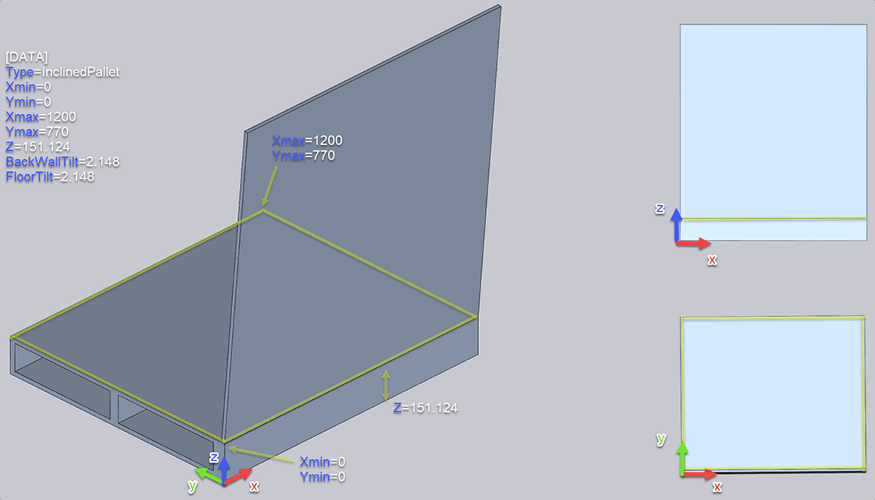
Note that the point Ymin=0 should be at the "inner corner" of the pallet, as indicated by the yellow mark in the figure above. The height of the pallet, measured at this inner corner point, must also be taken into account. This must be set in the INI file for the pallet.
[DATA]
Type=InclinedPallet
Xmin=0
Ymin=0
Xmax=1200
Ymax=770
Z=151.124
BackWallTilt=2.148
FloorTilt=2.148
Note that the Z height measured in the above figure was entered in the Z parameter.
The "FloorTilt" parameter determines the angle of inclination of the deposit floor to be specified in degrees (in this pallet, it is similar to the "BackWallTilt" angle (deposit wall angle of inclination), the inner angle here is 90 degrees).
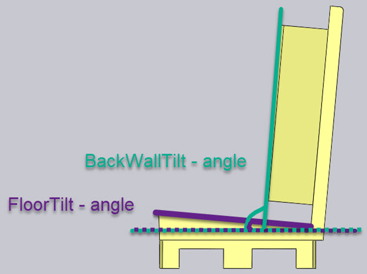
With this pallet, inclined stacking can be used to stack the parts correctly:
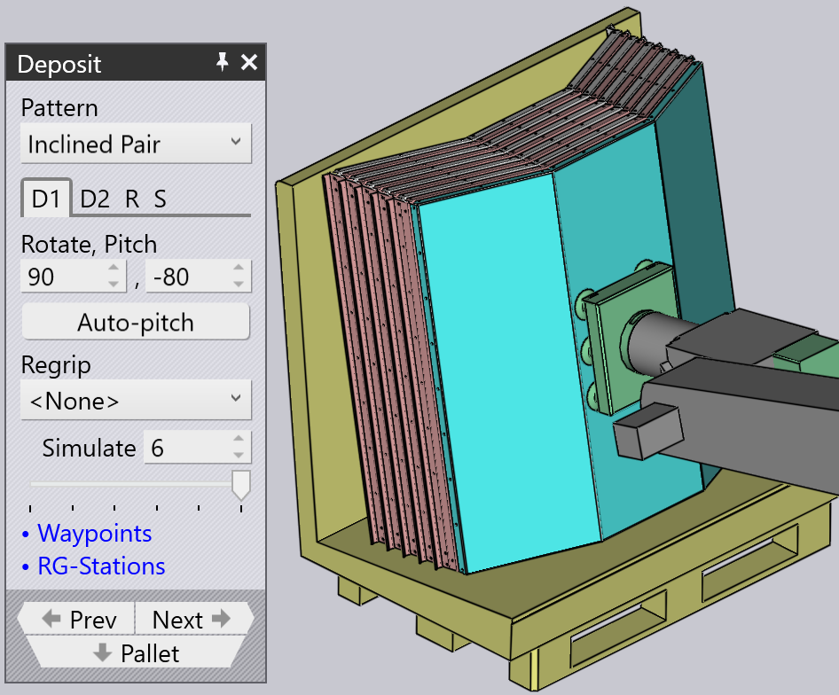
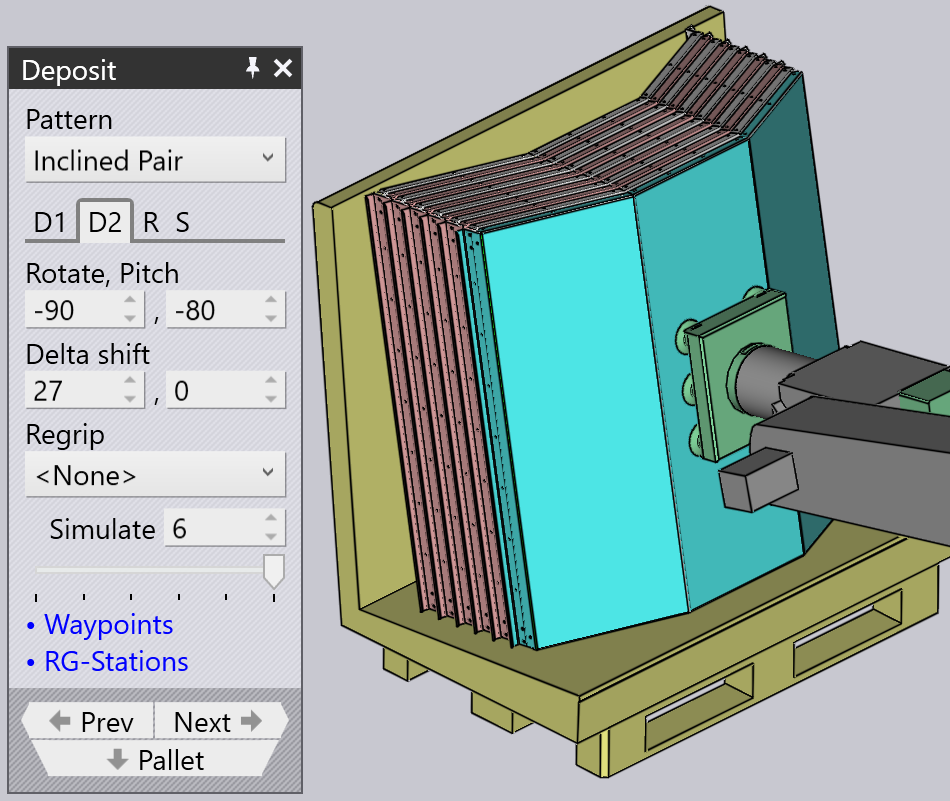
The "Pitch" was set to -80 via the "Auto-pitch" command, and the "delta shift" was manually set to 27 mm to optimize the stacking of the parts.
Pallet
A user-defined 3D model can be imported as a type "Pallet" and can be used for the pick-up and unload processes.
The INI file must contain the "Type=Pallet" for the system to treat it as a pallet.
The Xmin/Ymin and Xmax/Ymax values should indicate the boundaries of the yellow pick-up/unloading area.
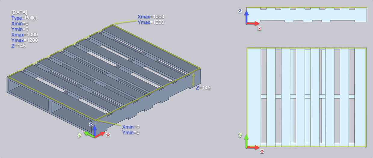
[DATA]
Type=Pallet
Xmin=0
Ymin=0
Xmax=1000
Ymax=1200
Z=145
Basket
A user-defined 3D model can be imported as a "Basket" type and used for unloading. A basket model serves as the example here, the yellow area is the area of the basket in which the unloading can take place.
The INI file must contain the "Type=Basket" so that the system treats it as a basket.
The Xmin/Xmax and Ymin/Ymax values should indicate the boundaries of the yellow unloading area.
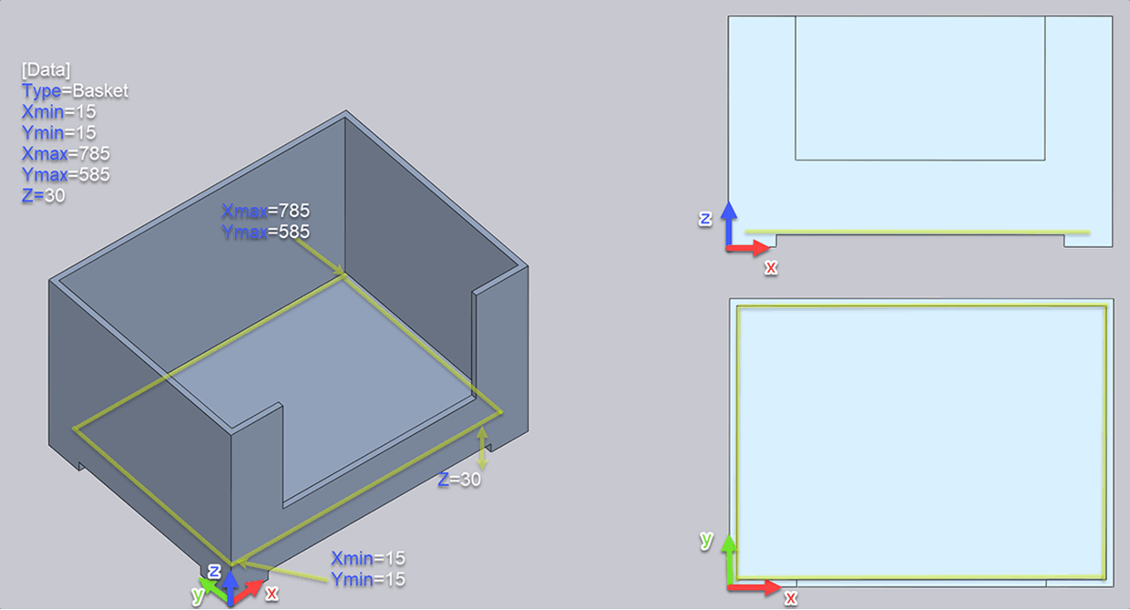
[DATA]
Type=Basket
Xmin=15
Ymin=15
Xmax=785
Ymax=585
Z=30
STOPA pallet
A user-defined 3D model can be imported as a type "STOPA" and can be used for the pick-up and unload processes. The example here is a STOPA model, the yellow area is the area of the conveyor in which pick-up or unloading can be done.
The INI file must contain the "Type=STOPA" for the system to treat it as a STOPA pallet.
The Xmin/Ymin and Xmax/Ymax values should indicate the boundaries of the yellow pick-up/unloading area.
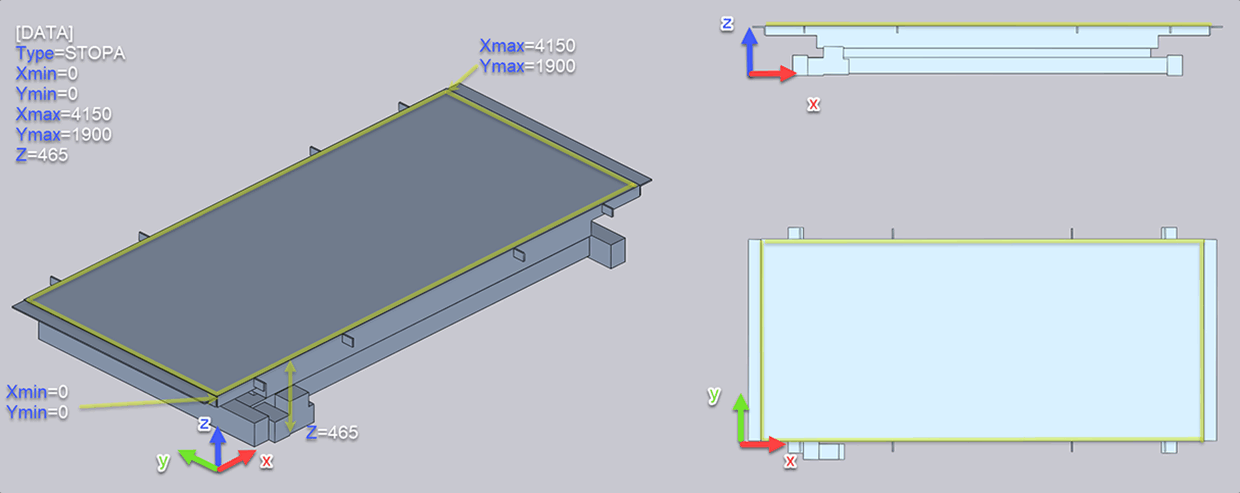
[DATA]
Type=STOPA
Xmin=0
Ymin=0
Xmax=4150
Ymax=1900
Z=465
Conveyor belt
A user-defined 3D model can be imported as a "Conveyor" type and be used for the pick-up and unloading processes.
The INI file must contain the "Type=Conveyor" for the system to treat it as a conveyor belt.
The X and Y values should indicate the boundaries of the yellow pick-up/unload area.
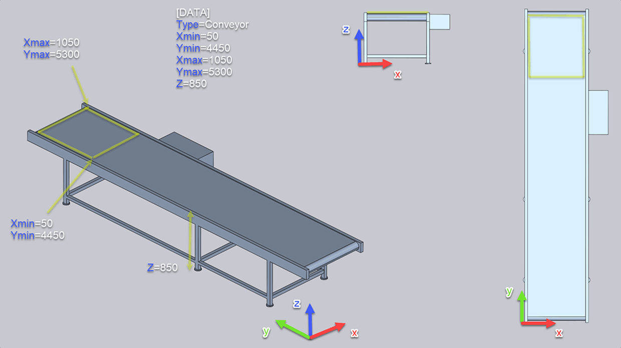
[DATA]
Type=Conveyor
Xmin=50
Ymin=4450
Xmax=1050
Ymax=5300
Z=850