
Finishing rules
Flux uses a system of Finishing rules to determine what to do when the cutting of a hole or a part is complete. As these holes and parts get detached from the sheet (by the laser cutting), various things can happen:
-
Very small slugs can fall through the gaps between the pins (or the slats) supporting the sheet (this is fine and causes no issues).
-
Very small parts may similarly fall through the pins, and this is not desirable (since these parts need to be retrieved). Ideally, these are wirejointed to the sheet, so they can be retrieved out with the sheet.
-
Large slugs and parts will be supported by a sufficient number of pins that they will remain stable on the machine table (this is fine).
-
Slugs or parts of an intermediate size can cause issues because they may not be supported sufficiently and can tilt, and the raised part of the part can collide over the laser head when it moves overhead.
-
Even if the part seems sufficiently supported by the pins, the nozzle cutting close to it may cause issues because of the pressure exerted by the gas blow from the nozzle. This dynamic pressure can cause the part to tilt, causing a collision.
Finishing rules are used to avoid these issues. When a part or slug is determined to be unstable or a collision hazard, there are some options:
-
One or more microjoints can be added to hold the part or slug tethered to the sheet. These will later be broken off as a post-processing step after thesheet is removed from the laser machine.
-
Slugs can be sliced up into smaller pieces that will all fall through the gaps between the slats.
Setting up finishing rules
Finishing rules are set up in the Cut CAM page of the Settings dialog.
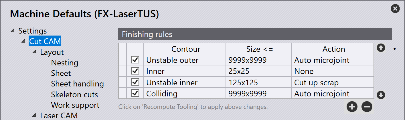
Each rule specifies a type of contour, a size and the action that should be taken when a match happens. The ordering of these rules is important. As Flux finishes processing each contour, it walks through these rules and applies the first one that matches. In general, this means that you need to write more specific rules first, or use smaller sizes first. (The Up and Down buttons next to the rules can be used to shuffle them up and down).
Contour types
-
All matches all contours (holes or outer contours).
-
Stable matches all contours that will remain stable on the slats or pins.
-
Stable inner is the set of inner contours that are stable.
-
Stable outer is the set of outer contours that are stable.
-
-
Unstable matches all contours that will either tilt or that will fall through the pins.
-
Unstable inner is the set of inner contours that are unstable.
-
Unstable outer is the set of outer contours that are unstable.
-
-
Colliding matches all contours that are unstable, and are also close to another contour on the part. When an unstable inner contour is close to another unstable inner contour, both are marked as potentially colliding, since it is not fixed which one of these will get cut first (and that sequence may be changed as the part is placed in a layout). When an unstable inner contour is close to an unstable outer contour, only the inner contour is tagged as colliding (since that will always be cut before the other one).
-
Colliding inner is the set of inner contours that are classified colliding.
-
Colliding outer is the set of outer contours that are classified colliding.
-
The analysis to determine whether a contour is Stable, or Colliding is compex.
The Stability Computation section below explains some of this complexity.
Actions
The Contour Type and Size are used to set up the criteria against which each contour is checked as it is tooled up. When a match is found (with the rules being evaluated in order), the corresponding Action is performed on that contour.
-
None: No special action is taken.
-
Auto microjoint: Applies one or more microjoint(s) on the contour. The number of microjoints needed is determined automatically (see the Stability Computation section below).
-
Cut up scrap: Cuts up slugs from holes into smaller pieces that will fall through the slats. The size of the scrap is set up in the Cut CAM page of the Settings dialog.
-
One microjoint, Two microjoints and Three microjoints: Create a precise number of microjoints on the contour.
Stability computation
The tilt-stability computations depend on the position of the contours relative to the support pins of the machine. To understand the results of this analysis, it is useful to turn on the display of the support pins from the Cut View page of the settings dialog:
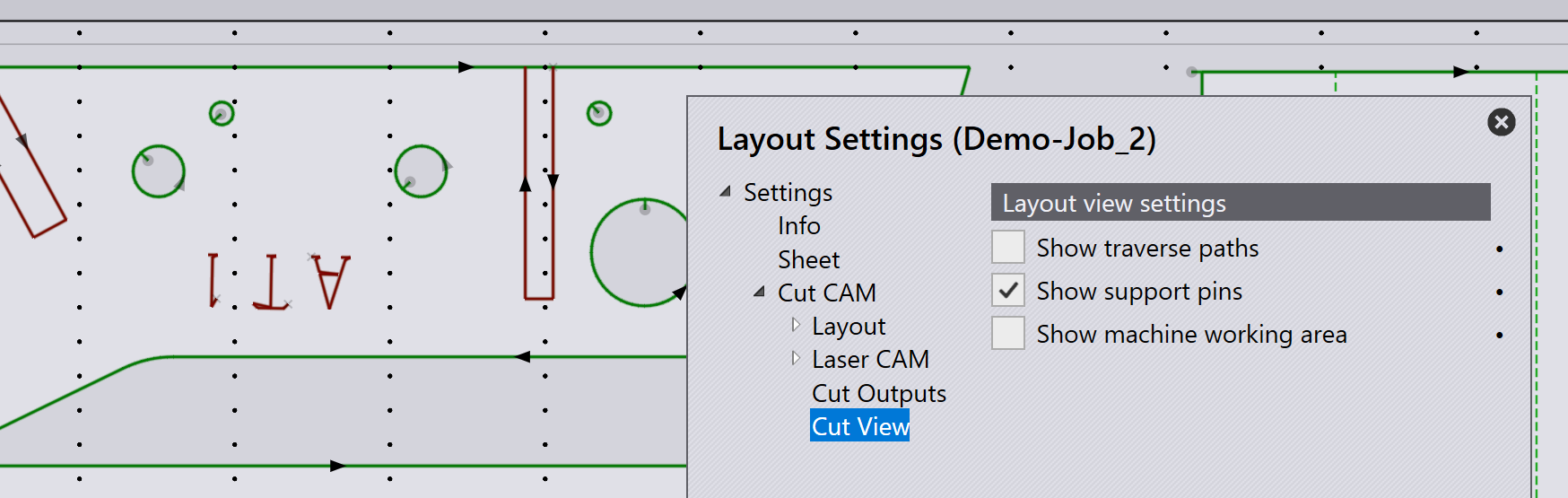
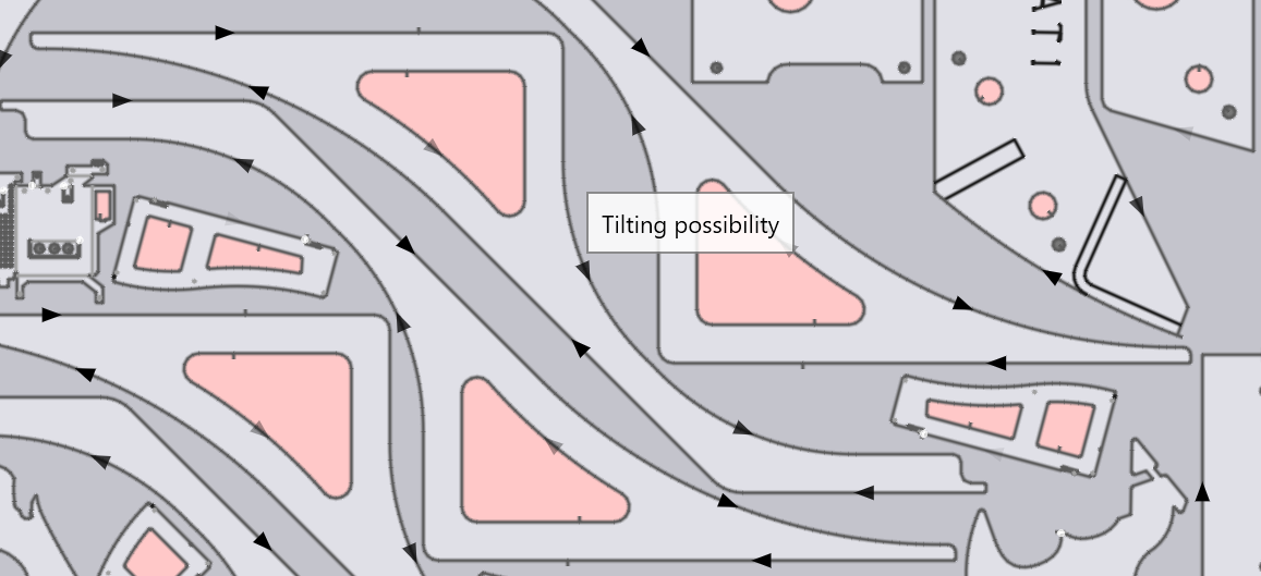
The software automatically recognizes whether a part could tilt on a layout. Possible tilting/unstable parts will be marked with red coloured contours on the layout, therefore allowing adjustment to the finishing rules before processing the job.
Adding microjoints
Here is an example where Flux has added micro-joints to to some holes that are very close to outer contours (or to other holes). When the nozzle passes so close during the cutting of those other holes, it is possible for this slug to tilt up due to the gas pressure and cause a collision. So a microjoint is added.
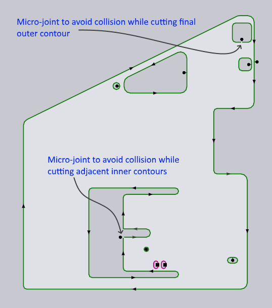
Note that no microjoint was needed for the even smaller hole nearby, since that is small enough to safely fall through the gaps in the pins.
Torque on microjoints
Here is a more extreme example, where a single microjoint may not be enough.
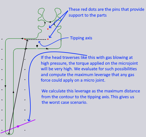
As explained in the image, when head moves over the long protrusion near the bottom of the contour, the resulting torque on the microjoint (because of the long lever arm) can cause it to break off, and additional microjoints are added automatically to counteract that if the Auto microjoint action has been specified in the finishing rule that applies for this contour.
Shifting approach points
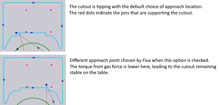
Sometimes choosing a different approach point can change an unstable contour into a stable contour, as shown above. Flux detect such situations and automatically adjust the approach point.
Part-in-part nesting
A large inner hole contour may be supported by a sufficient number of pins and could be judged Stable. No particular finishing action might be applied for this hole, since the slug would rest stably on the pins (as shown on the image below left):
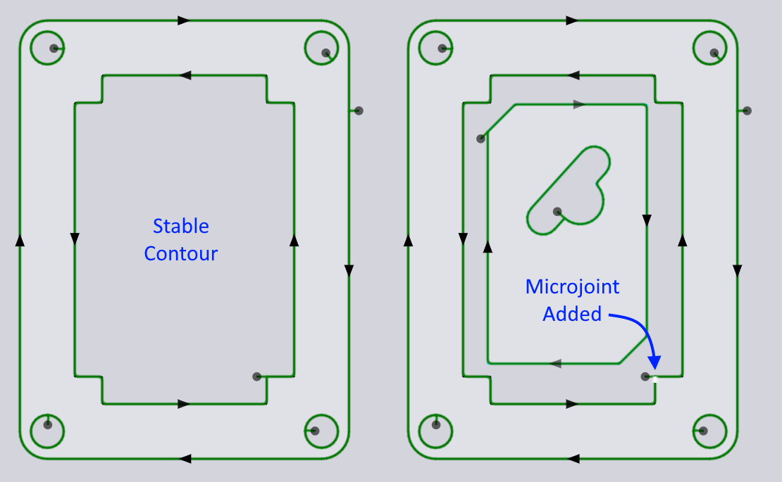
In a layout, a smaller part might be nested in this hole to improve sheet utilization and at that point, the inner contour may not be supported with enough pins to be considered stable. Flux will add a microjoint to stabilize the contour, as shown in the image above right.
If the smaller part nested in that hole is subsequently removed, the microjoint goes away too.