
Bending Aids
Bending Aids are press brake machine components that help to bend thicker sheet metals. They are designed to provide additional support and control during the bending process, ensuring accurate and consistent results.
A press brake can have multiple bending aids or a single bending aid installed, depending on the specific requirements of the bending operation.
| Bending aids are applicable only for TruBend 5000 and 8000 series. |
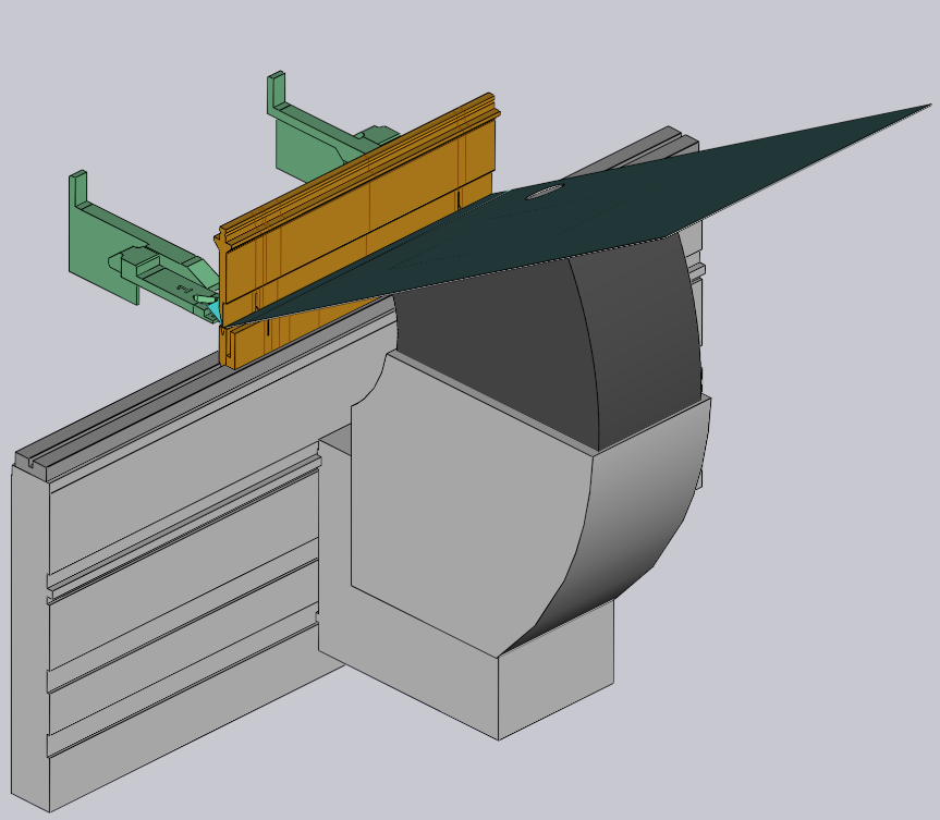
Configuring Bending Aids
Bending Aids can be configured in Database / Machines / Settings.
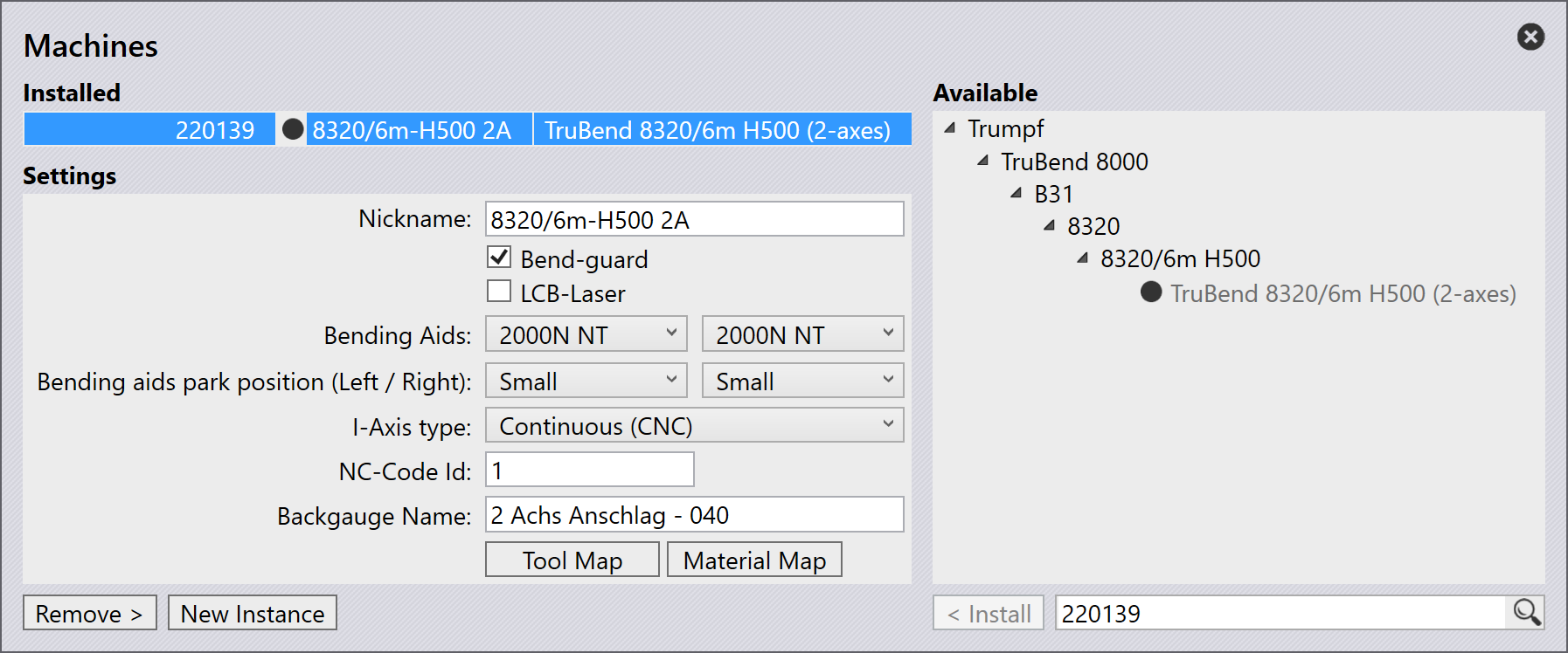
When a part is imported and a machine with bending aids is selected, Flux automatically configures the bending aids based on the part’s requirements.
Using Bending Aids
Once a feasible bending solution is generated, the bending aids can further be adjusted to optimize the bending process.
Click directly on the bending aid in Flux to open the Bend Aid panel. The number in the bend aid panel represents the bending sequence.
![][Bending Aid Panel](img/bendaidpanel.png)
-
Index - Denotes the currently selected bending aid.
-
Position (Z,R) - Used to adjust the position of the bending aid along Z and R axes.
-
Enabled - Select this checkbox to activate the bending aid.
-
Auto-Place - Used to automatically position the bending aid based on the part’s geometry.
Speed:
-
Down - Used to adjust the retraction speed of the bending aid post bend operation.
-
Set All Bends - Used to apply the current speed setting to all bends in the sequence.
Advanced:
-
Method - Used to define the operational mode of the bending aid. Options include:
-
Default - Resets the bending aid settings to default values.
-
Return at UDP - Configures the bending aid to return to a user-defined position after each bend.
-
Tilt product - Enables the bending aid to tilt the part during the bending process for better alignment.
-
Static angle - Allows setting a fixed angle for the bending aid during operation.
-
-
Stop angle - Used to set the angle at which the bending aid will stop during operation.
Bending Aids parking position
Bending Aids can be parked in a designated position when not in use. This helps to optimize the workspace and ensures safety during operation. This also prevents collisions with other machine components.
Bending Aids can be parked in the following positions:
-
Default - Bending aids can be parked until the table length.
-
Small - Bending aids can be placed 700 mm beyond table length.
-
Large - Bending aids can be placed 1200 mm beyond table length.
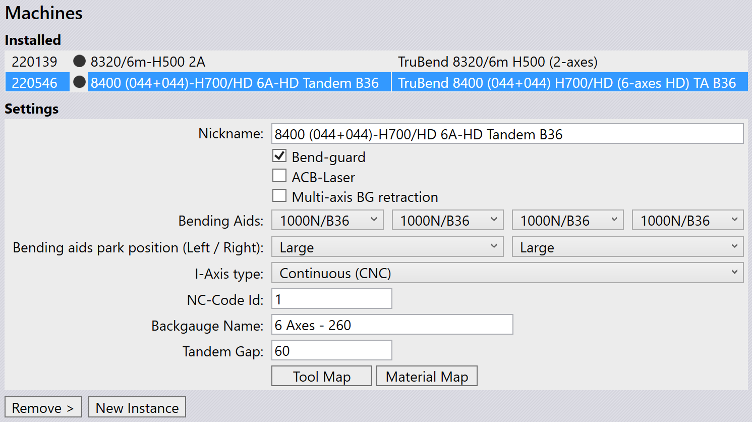
For tandem machines, there are four bending aids available. For left tandem machines, only left side parking is allowed. For right tandem machines, only right side parking is allowed.
|
The park position option will be displayed only for TruBend 8000 series and VarioPress machines. For B36 tandem machines, the parking position small is not applicable. |
Creating custom bending aids
In order to create custom bending aids in Flux, you first need to create an ini file that defines the bending aid’s parameters and mesh files for the bending aid components (Carriage, Table, and Plate).
[BAData]
; The user defined name of the BendAid. Only used for custom bend aids
Name=BATest
; The range of V-widths the bend aid can support
DieV=16,250
; The range of die-heights the bend aid can support
DieHeight=-30,250
; Maximum angle, in degrees
MaxAngle=55
; Lift capacity, in kg
Payload=300
; Maximum lift speed, in degrees/second
Speed=45
; When the bending aid is at X=0, this is the bound of the support table in top view
Table=-159,-1032,159,-245.6
; The X-Span of the bending aid (when positioned at 0)
XExtent=-213,213
; Tells whether the user can change the forward speed
CanChangeForwardSpeed=False
; Tells whether safety stop angle is possible in the machine
CanStopAtReturn=True
; Can the bending aid movement be varied using different methods?
AdvancedControl=True
; What type of existing bending aid can this be mapped to? Used only by custom bend aids
EType=TB8000_2000N_B36

[Carriage]
Model=Carriage.mesh
Stroke=-1000,1000
Color=White
Shift=0,0,100

[Table]
Model=Table.Mesh
Stroke=50,200
Color=White

[Plate]
Model=Plate.mesh
Stroke=0,56
Color=#4A4A4A
Place the ini file and the corresponding mesh files in a folder which can then be imported into Flux.
Importing custom bending aids
To import custom bending aids:
-
Navigate to File / Import / Bending Aids… and select the already created ini file (ensure the corresponding mesh files are in the same folder).
-
The imported bending aids will then be available in the bending aid selection dropdown in the machine settings.
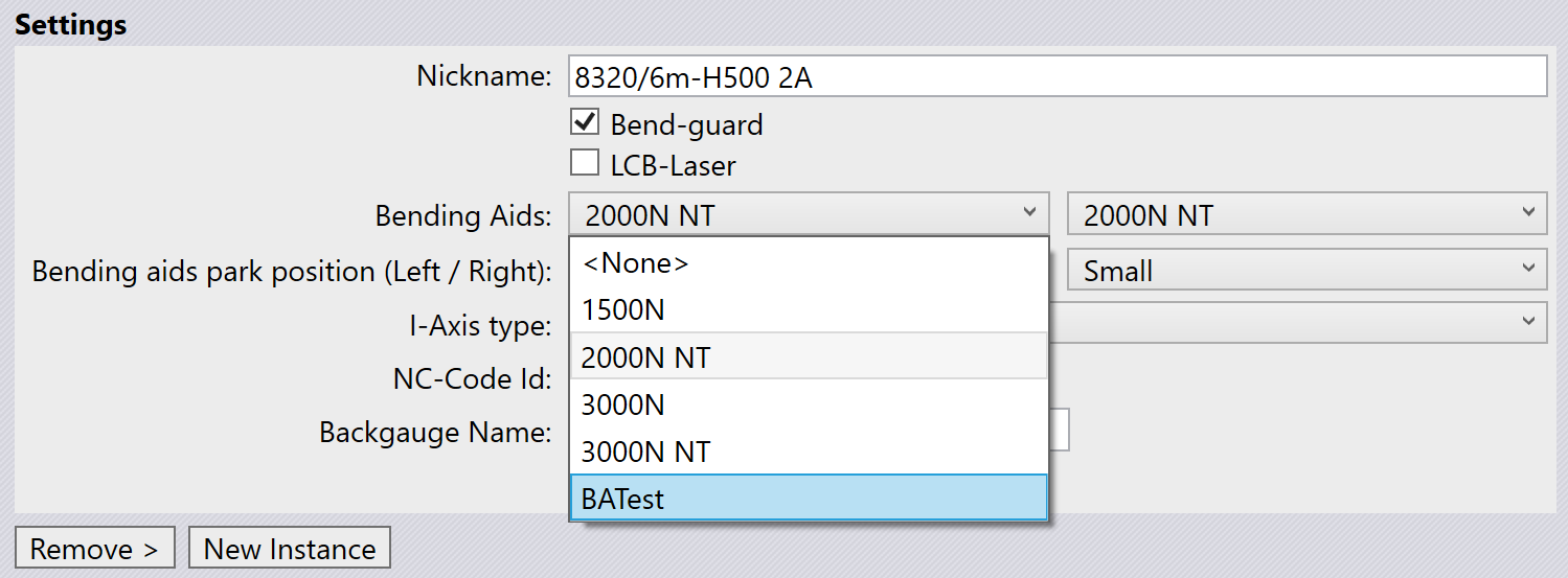
This option is useful when a bending aid needs to be customized for specific bending tasks or when using specialized bending aids not included in the default Flux database.