
Flux Reference Manual

  • Welcome to Flux
  • Introduction
    • Installing the software
    • The user interface
    • Part workflow
  • CAD
    • 2-D Import
      • 2-D Cleanup
    • 3-D Import
      • Import 3D Model
      • Import assembly
      • Form detection
      • Component detection
    • Modifying the geometry
    • Attachments
  • Cut CAM
    • Part workflow
      • Editing panels
        • Laser cut
          • Approach
          • Withdrawal
          • Microjoint
          • Advanced
        • Contour
        • Scrap cut
        • Part
        • Corner treatment
      • Quick-Nest
    • Job workflow
      • Job panel
        • Sheets tab
        • Parts tab
        • Layouts tab
        • Summary tab
      • Edit layout
        • Nesting modes
        • Placement panel
        • Sequencing
        • Slice sheet
    • Bevel cut
      • Open contours
      • Variable bevel
      • Miscellaneous
    • Advanced
      • Finishing rules
      • Edit LTT
      • FlyLine
      • TwinLine
        • Strategy
        • Microjoints
        • Further settings
      • DetectLine
  • Bend CAM
    • Create bend data
    • Bend navigator
    • Edit bend data
      • Edit a bend
      • Edit a tool mount
      • Edit a bend setup
      • Edit the back-gauges
      • Edit angle measurement
      • Bends spreadsheet
      • Changing the sequence
      • Adding setups and stations
    • Advanced
      • Angle measurement
      • Batch process
      • Recompute solution
      • Tonnage check
    • Bending Aids
  • BendMaster CAM
    • Bend navigator
    • Part pickup
      • Pickup from pallet
      • Pickup from dispenser
    • Robotic bending
      • Insertion
      • Bending
      • Extraction
    • Regripping
      • Regrip panel
      • Add regrip
      • Edit regrip
      • Regrip with jaw
      • RG-Stations panel
    • Part deposit
      • Deposit pattern types
      • Deposit tabs
      • Add separator sheets
      • Lock part-rest
    • Advanced
      • Waypoints
      • Cell configuration
      • Custom Cell Components
      • Gripper database
        • Create a gripper
        • Import gripper from DXF
        • Import Suction Cup
  • Flex Cell CAM
    • Bend navigator
    • Part pickup
      • Pickup from pallet
      • Centering table
    • Robotic bending
      • Strategy panel
    • Regripping
      • Regrip panel
      • Add/Remove regrip
      • Gripper Panel
      • Double Sheet Station
    • Part deposit
      • Deposit Tabs
    • Advanced
      • Waypoints
    • Troubleshooting
  • Fold CAM
    • Create fold data
    • The Fold view
    • Editing Fold data
      • Edit a bend
      • Edit a side/section
      • Change the sequence
      • Edit the blank-holders
      • Edit the gauging
      • Edit the blades
      • Edit the loading
      • Edit the unloading
    • Tool inventory
    • Advanced
      • Custom air-gap tables
      • Manual bend completion
      • Required flange length
  • Settings
    • Drawing
      • Layers
      • Dimensions
      • View
    • Bend CAM
      • Machine defaults
      • Bend outputs
      • Bend view
      • Bend cell
    • Cut settings
      • Cut CAM
      • Layout
        • Nest settings
        • Sheet
        • Sheet handling
        • Skeleton cuts
        • Work support
      • Laser CAM
        • Sequence
      • Cut outputs
      • Cut view
    • Panel bending
      • Defaults
      • ZBW carriers
      • Outputs
    • Reports
      • Item defaults
    • Import/Export
    • Environment
  • Database
    • Materials
    • Machines
    • Bend tools
    • Bend deductions
    • Bend grippers
    • Forms and Components
  • Reports
    • Report designer
    • Fields, pictures and tables
    • Bands (sub-reports)
    • Labels, bitmaps and shapes
  • Appendix
    • Supported 3D formats
    • Separator sheet DXF
    • Bend tool DXF
    • The Adapt Geometry feature
Flex Cell CAM
/
Part deposit
/
Deposit Tabs

Deposit Tabs

The Deposit panel has the following tabs:
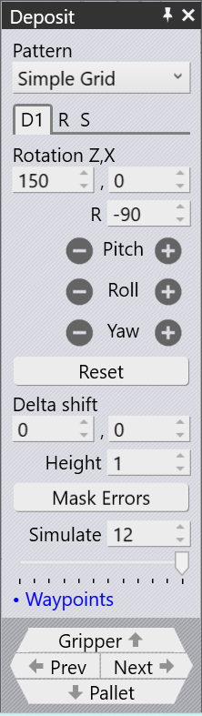
Deposit panel

  • Part deposit settings (D1, D2,…​.,Dn)

  • Repeat grid (R)

  • Deposit sequence (S)

Part 1 settings (D1)

The orientation and other settings for the parts are edited in the D1 tab. Use this D1 tab to handle the part deposit settings to drop parts over the deposit.

  • Rotation Z, X and R: At these fields, part rotation angles can be set. The Z, X and R rotation is with respect to machine coordinates. The rotation order must be set in sequence: Z → X → R.

  • Pitch, Roll and Yaw: The Pitch, Roll and Yaw can be edited using the DepositControl1 and DepositControl2 controls. These rotations are with respect to tip coordinate system. When these are edited, the part rotation angle (Z, X and R) values will be updated accordingly.

  • Reset: This button resets the part rotation angles to default values.

  • Delta Shift: This option is used to shift each successive part in the deposit relative to the part underneath. This setting is available only when the Simple Grid or Conveyor pattern is selected for the deposit operation.

  • Height: This parameter controls the height above the stack from which the part is released (the part falls by this distance when coming to rest on the stack).

  • Simulate: The sequence or order in which each part is placed onto the pallet can be seen by using the Simulate option. The number of layers and grid utilized for the deposit determines what quantity is simulated. The part deposit simulation can be viewed by moving the simulate slider back and forth.
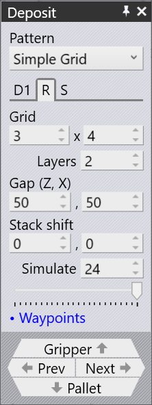
Repeattab

Repeat Grid (R)

The D1 tab shown above is used to specify the orientation of the first part of the deposit. Then, the settings in the Repeat tab are used to replicate that into a grid of rows (Z), columns (X) and layers.

  • Grid: These settings are used to set up the number of columns and rows in the deposit.

  • Layers: This setting specifies how many parts are stacked on top of each other in each pile.

  • Gap (Z, X): These settings are used to specify the gap between successive columns or successive rows. If you set this to 0, the rows or columns are exactly touching each other.

  • Stack shift: These settings are used to displace the complete stack of all the parts away from the center of the pallet.

  • Simulate: This option allows you to simulate the deposit sequence to visualize the order in which parts are placed on the pallet.

Deposit Sequence (S)
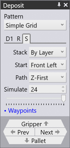
depsequencetab

The Sequence tab is used to control the sequence in which the parts are deposited.

  • Stack: This setting has two options: By Layer or By Pile. In this example here, stacking By Layer would build up both the adjacent piles in unison

    • this means that successive deposits would happen in pile 1, pile 2, pile 1, pile 2 etc. Thus both the piles will rise in height together. When you stack By Pile, all the parts of the pile on the left are deposited first before we start placing any parts on the right pile.

  • Start corner and Path: These settings are used when there are multiple rows or columns, and decide which corner the stacking starts from, and whether the stacking then proceeds row-by-row, or column-by-column. This can be useful especially with an off-center gripper, since a different starting corner may cause a collision between the gripper and the previous part that was already deposited.

  • Simulate: Both the number spinner and the slider can be used to scrub through the deposits to see the order in which they happen on the pallet.

Contents

  • Part 1 settings (D1)
  • Repeat Grid (R)
  • Deposit Sequence (S)
Part deposit Advanced

      Copyright © 2026 TRUMPF Metamation. All rights reserved.

    Compiled by Bento