Flux Reference Manual

  • Welcome to Flux
  • Introduction
    • Installing the software
    • The user interface
    • Part workflow
  • CAD
    • 2-D Import
      • 2-D Cleanup
    • 3-D Import
      • Import 3D Model
      • Import assembly
      • Form detection
      • Component detection
    • Modifying the geometry
    • Attachments
  • Laser CAM
    • Part workflow
      • Editing panels
        • Laser cut
          • Approach
          • Withdrawal
          • Microjoint
          • Advanced
        • Contour
        • Scrap cut
        • Part
        • Corner treatment
      • Quick-Nest
    • Job workflow
      • Job panel
        • Sheets tab
        • Parts tab
        • Layouts tab
        • Summary tab
      • Edit layout
        • Nesting modes
        • Placement panel
        • Sequencing
        • Slice sheet
    • Bevel cut
      • Open contours
      • Variable bevel
      • Miscellaneous
    • Advanced
      • Finishing rules
      • Edit LTT
      • FlyLine
      • TwinLine
        • Strategy
        • Microjoints
        • Further settings
      • DetectLine
  • Bend CAM
    • Create bend data
    • Bend navigator
    • Edit bend data
      • Edit a bend
      • Edit a tool mount
      • Edit a bend setup
      • Edit the back-gauges
      • Edit angle measurement
      • Bends spreadsheet
      • Changing the sequence
      • Adding setups and stations
    • Advanced
      • Angle measurement
      • Batch process
      • Recompute solution
      • Tonnage check
    • Bending Aids
  • BendMaster CAM
    • Bend navigator
    • Part pickup
      • Pickup from pallet
      • Pickup from dispenser
    • Robotic bending
      • Insertion
      • Bending
      • Extraction
    • Regripping
      • Regrip panel
      • Add regrip
      • Edit regrip
      • Regrip with jaw
      • RG-Stations panel
    • Part deposit
      • Deposit panel
      • Repeat and sequence
      • Add separator sheets
      • Lock part-rest
      • Deposit pattern types
    • Advanced
      • Waypoints
      • Cell configuration
      • Custom Cell Components
      • Gripper database
        • Create a gripper
        • Import gripper from DXF
        • Import Suction Cup
  • FlexCell CAM
    • Bend navigator
    • Part pickup
      • Pickup from pallet
      • Centering table
    • Robotic bending
      • Insertion
      • Bending
      • Extraction
      • Advanced
    • Regripping
      • Regrip panel
      • Add/Remove regrip
      • Gripper Panel
      • RG-Stations panel
    • Part deposit
      • Deposit panel
      • Deposit Tabs
    • Advanced
      • Waypoints
      • Cell configuration
      • Gripper database
        • Create a gripper
        • Import gripper from DXF
    • Troubleshooting
  • Fold CAM
    • Create fold data
    • The Fold view
    • Editing Fold data
      • Edit a bend
      • Edit a side/section
      • Change the sequence
      • Edit the blank-holders
      • Edit the gauging
      • Edit the blades
      • Edit the loading
      • Edit the unloading
    • Tool inventory
    • Advanced
      • Custom air-gap tables
      • Manual bend completion
      • Required flange length
  • Settings
    • Drawing
      • Layers
      • Dimensions
      • View
    • Bend CAM
      • Machine defaults
      • Bend outputs
      • Bend view
      • Bend cell
    • Cut CAM
      • Layout
        • Nest settings
        • Sheet
        • Sheet handling
        • Skeleton cuts
        • Work support
      • Laser CAM
        • Sequence
      • Cut outputs
      • Cut view
    • Panel bending
      • Defaults
      • ZBW carriers
      • Outputs
    • Reports
      • Item defaults
    • Import/Export
    • Environment
  • Database
    • Materials
    • Machines
    • Bend tools
    • Bend deductions
    • Bend grippers
    • Forms and Components
  • Reports
    • Report designer
    • Fields, pictures and tables
    • Bands (sub-reports)
    • Labels, bitmaps and shapes
  • Appendix
    • Supported 3D formats
    • Separator sheet DXF
    • Bend tool DXF
    • The Adapt Geometry feature
Database
/
Bend deductions

Bend deductions

Bend deductions are used to calculate the developed length[1] of a sheet metal part. It is required to accurately produce parts with the correct dimensions after bending.

Bend deductions account for the material stretch and compression that occurs during the bending process. By using bend deductions, Flux can adjust the flat pattern length to ensure that the final bent part meets the specified dimensions.

Bend deductions can vary based on factors such as material type, thickness, bend radius, and bending method.

When a 3D part is imported into Flux, the software automatically calculates the bend deductions based on the part’s geometry and material properties. You can also manually adjust the bend deductions if needed to fine-tune the flat pattern length.

Bend deduction settings

Custom bend deductions can be set in the Bend Deductions database. To access, click on the database icon and select Bend Deductions.
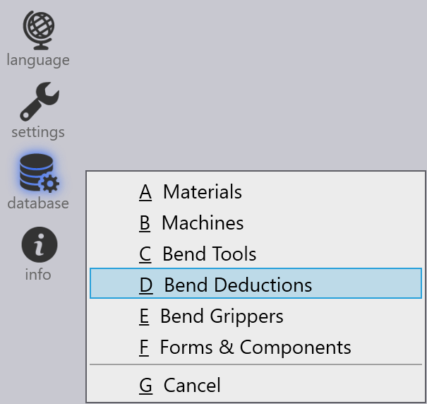
Bend Deductions

You can Add a new bend deduction scenario or select an existing scenario to Edit or Delete it. You can also Copy an existing scenario to create a new one with similar settings.
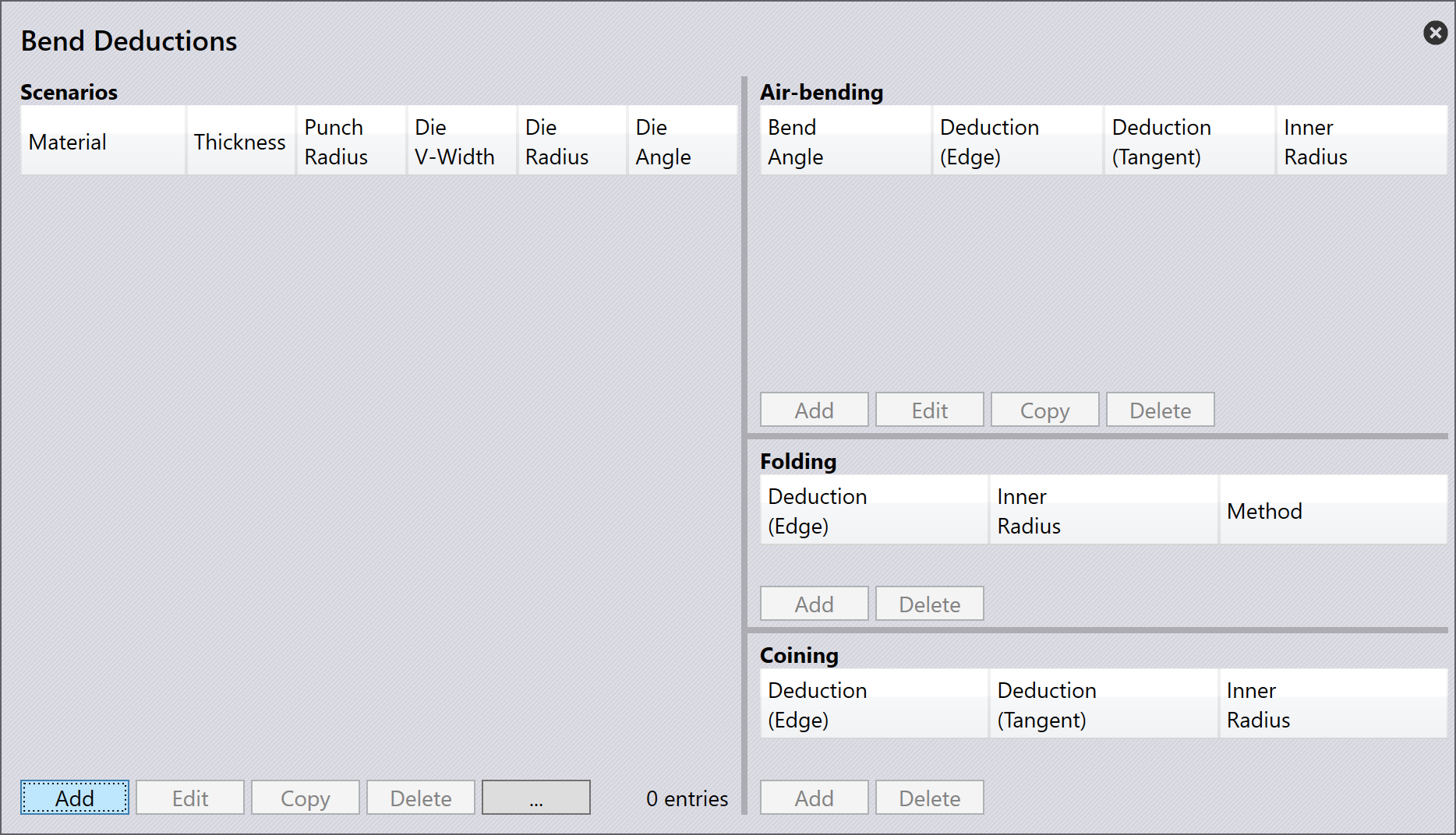
Bend Deductions dialog

Click Add to create a new bend deduction scenario. Select and type in the following parameters:

  • Material: Select the material for which the bend deductions apply.

  • Thickness: Set the thickness of the sheet for which the bend deductions apply.

  • Punch radius: Set the upper tool radius for which the bend deductions apply.

  • V-width type: Choose the type of V-width measurement used.

  • Die V-width: Set the lower tool width for which the bend deductions apply.

  • Die radius: Set the lower tool radius for which the bend deductions apply.

  • Die angle: Set the lower tool angle for which the bend deductions apply.

Click OK to save the new scenario.

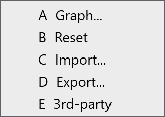
In addition to this, select a bend deduction scenario and click the …​ option to see further options:

Bend Deductions options
  • Graph: Displays a graph showing the relationship between bend angle and bend deduction. This visual representation helps to understand how bend deductions change with different bend angles. Move the cursor over the graph’s blue and red lines to see specific values.
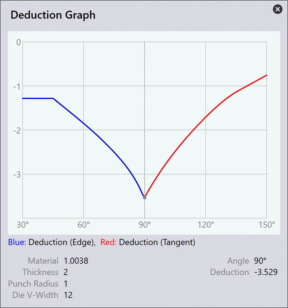
Deduction Graph
  • Import: Allows you to import bend deduction data from an external CSV file.

  • Export: Enables you to export the current bend deduction data to a CSV file for backup or sharing purposes.

  • 3rd party: Provides options to import bend deduction data from third-party software or sources.

Bend deduction types

Flux supports three types of bend deductions: Air Bending, Folding, and Coining.

Each type has its own set of parameters and calculations to accurately determine the bend deductions based on the bending method used.

Air Bending

Air bending is a common bending method where the sheet metal is bent using a punch and die without fully closing the die. This method allows for more flexibility and is suitable for a wide range of materials and thicknesses.

To add bend deductions for air bending, select a suitable scenario from the Bend Deductions database. Click Add to create a new air bending deduction scenario and type in the Bend Angle.
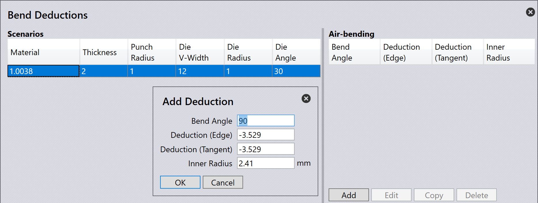
Air Bending Deduction

As you input the bend angle, the corresponding Deduction (Edge), Deduction (Tangent), and Inner Radius values will be calculated and displayed.

Click OK to save the new air bending deduction.

Folding

Folding or Hemming is a bending method where the sheet metal is bent using a punch and die that fully closes, creating a sharp bend. This method is often used for thinner materials and requires precise control of bend deductions.
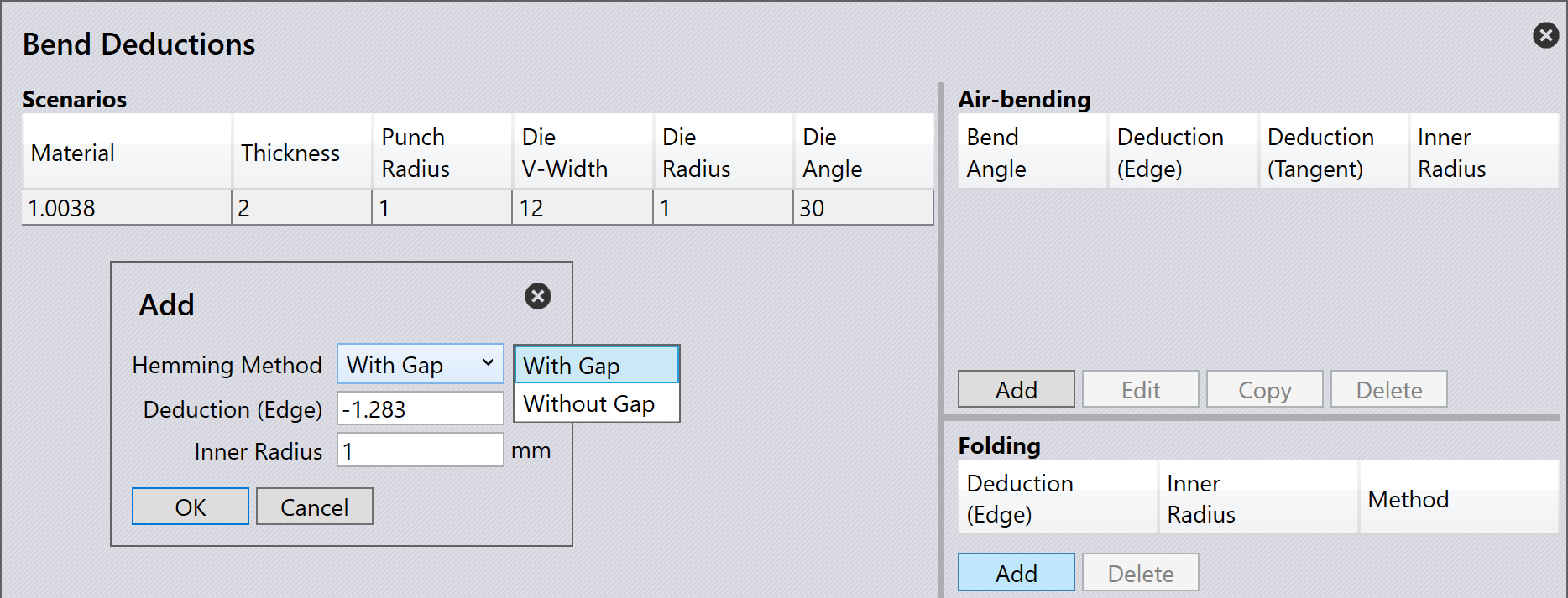
Folding Deduction

To add bend deductions for folding, select a suitable scenario from the Bend Deductions database. Click Add to create a new folding deduction scenario and select the Hemming method.

Click OK to save the new folding deduction.

Coining

Coining is a bending method where the sheet metal is pressed between a punch and die with high pressure, resulting in a precise and sharp bend. This method is typically used for thicker materials and requires accurate bend deductions.
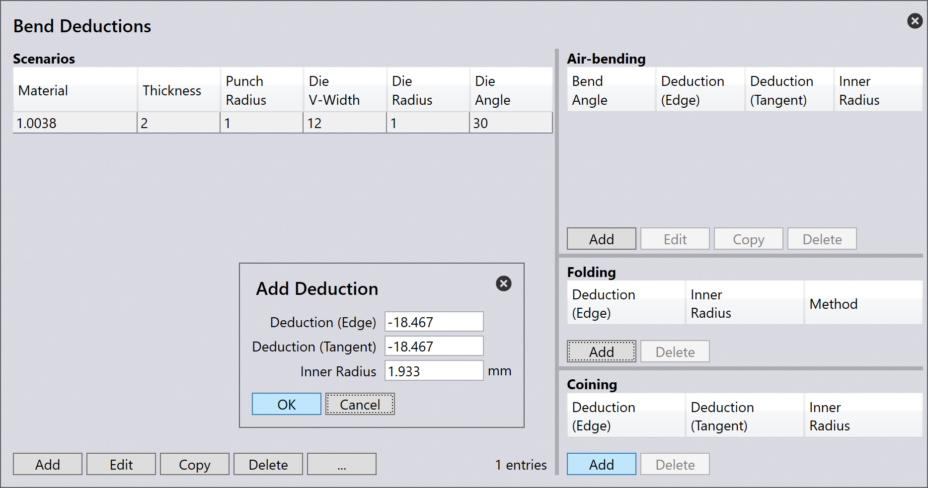
Coining Deduction

To add bend deductions for coining, select a suitable scenario from the Bend Deductions database. Click Add to create a new coining deduction scenario.

Click OK to save the new coining deduction.


1. The developed length is the total length of the flat sheet metal before bending. This is the actual length of the flat pattern which is cut (using laser cutter) and formed (using press brake) to create the final part.

Contents

  • Bend deduction settings
  • Bend deduction types
  • Air Bending
  • Folding
  • Coining
Bend tools Bend grippers

      Copyright © 2025 TRUMPF Metamation. All rights reserved.

    Compiled by Bento