
Flux Reference Manual

  • Welcome to Flux
  • Introduction
    • Installing the software
    • The user interface
    • Part workflow
  • CAD
    • 2-D Import
      • 2-D Cleanup
    • 3-D Import
      • Import 3D Model
      • Import assembly
      • Form detection
      • Component detection
    • Modifying the geometry
    • Attachments
  • Cut CAM
    • Part workflow
      • Editing panels
        • Laser cut
          • Approach
          • Withdrawal
          • Microjoint
          • Advanced
        • Contour
        • Scrap cut
        • Part
        • Corner treatment
      • Quick-Nest
    • Job workflow
      • Job panel
        • Sheets tab
        • Parts tab
        • Layouts tab
        • Summary tab
      • Edit layout
        • Nesting modes
        • Placement panel
        • Sequencing
        • Slice sheet
    • Bevel cut
      • Open contours
      • Variable bevel
      • Miscellaneous
    • Advanced
      • Finishing rules
      • Edit LTT
      • FlyLine
      • TwinLine
        • Strategy
        • Microjoints
        • Further settings
      • DetectLine
  • Bend CAM
    • Create bend data
    • Bend navigator
    • Edit bend data
      • Edit a bend
      • Edit a tool mount
      • Edit a bend setup
      • Edit the back-gauges
      • Edit angle measurement
      • Bends spreadsheet
      • Changing the sequence
      • Adding setups and stations
    • Advanced
      • Angle measurement
      • Batch process
      • Recompute solution
      • Tonnage check
    • Bending Aids
  • BendMaster CAM
    • Bend navigator
    • Part pickup
      • Pickup from pallet
      • Pickup from dispenser
    • Robotic bending
      • Insertion
      • Bending
      • Extraction
    • Regripping
      • Regrip panel
      • Add regrip
      • Edit regrip
      • Regrip with jaw
      • RG-Stations panel
    • Part deposit
      • Deposit pattern types
      • Deposit tabs
      • Add separator sheets
      • Lock part-rest
    • Advanced
      • Waypoints
      • Cell configuration
      • Custom Cell Components
      • Gripper database
        • Create a gripper
        • Import gripper from DXF
        • Import Suction Cup
  • Flex Cell CAM
    • Bend navigator
    • Part pickup
      • Pickup from pallet
      • Centering table
    • Robotic bending
      • Strategy panel
    • Regripping
      • Regrip panel
      • Add/Remove regrip
      • Gripper Panel
      • Double Sheet Station
    • Part deposit
      • Deposit Tabs
    • Advanced
      • Waypoints
    • Troubleshooting
  • Fold CAM
    • Create fold data
    • The Fold view
    • Editing Fold data
      • Edit a bend
      • Edit a side/section
      • Change the sequence
      • Edit the blank-holders
      • Edit the gauging
      • Edit the blades
      • Edit the loading
      • Edit the unloading
    • Tool inventory
    • Advanced
      • Custom air-gap tables
      • Manual bend completion
      • Required flange length
  • Settings
    • Drawing
      • Layers
      • Dimensions
      • View
    • Bend CAM
      • Machine defaults
      • Bend outputs
      • Bend view
      • Bend cell
    • Cut settings
      • Cut CAM
      • Layout
        • Nest settings
        • Sheet
        • Sheet handling
        • Skeleton cuts
        • Work support
      • Laser CAM
        • Sequence
      • Cut outputs
      • Cut view
    • Panel bending
      • Defaults
      • ZBW carriers
      • Outputs
    • Reports
      • Item defaults
    • Import/Export
    • Environment
  • Database
    • Materials
    • Machines
    • Bend tools
    • Bend deductions
    • Bend grippers
    • Forms and Components
  • Reports
    • Report designer
    • Fields, pictures and tables
    • Bands (sub-reports)
    • Labels, bitmaps and shapes
  • Appendix
    • Supported 3D formats
    • Separator sheet DXF
    • Bend tool DXF
    • The Adapt Geometry feature
Settings
/
Cut settings

Cut settings

The Flux settings page for cut module is available under different names, depending on the sheet metal part processing stage.

The following sections are available in Flux:

  1. Part settings - The first stage of sheet metal part processing. Configure part settings and application settings.

  2. Cut settings - The second stage of processing after tooling. Configure cut settings, machine defaults, and application settings.

  3. Layout settings - The third stage of processing after nesting. Configure layout settings, machine defaults, and application settings.

  4. Machine defaults - Contains the default settings for the selected machine.

  5. Application settings - Contains the general application settings for Flux.

Settings available in the Cut, Layout, and Machine defaults sections are also available in the Application settings section of the Flux settings page. When the same setting is defined in multiple sections, the settings hierarchy determines which value takes precedence.

Part settings
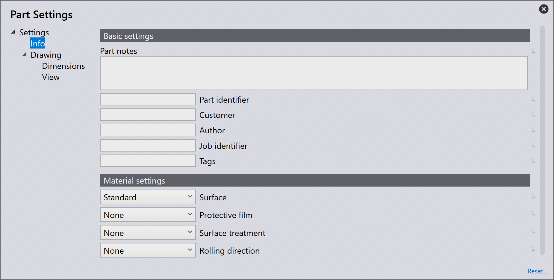
Part settings

Info - Basic settings

Part notes - Specifies notes related to the sheet metal part.

Part identifier - Specifies the unique identifier of the part.

Customer - Specifies the customer associated with the part.

Author - Specifies the name of the person who created the part.

Job identifier - Specifies the unique identifier of the associated job.

Tags - Specifies the tags assigned to the part.

Info - Material settings

Surface - Specifies the surface finish or treatment of the material.

Protective film - Indicates whether the material includes a protective film.

Surface treatment - Specifies the surface treatment applied to the material.

Rolling direction - Specifies the rolling direction of the material during manufacturing.

Dimensions
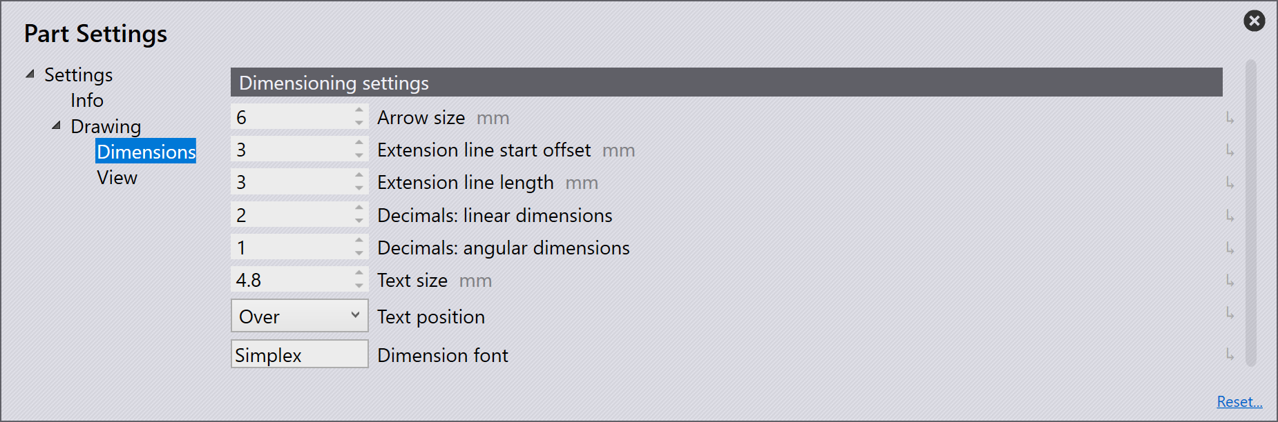
Dimension settings

Arrow size - Specifies the size of dimension arrows.

Extended line start offset - Specifies the offset between the start of the extension line and the dimensioned feature.

Extension line length - Specifies the length of dimension extension lines.

Decimals:linear dimensions - Specifies the number of decimal places displayed for linear dimensions.

Decimals:angular dimensions - Specifies the number of decimal places displayed for angular dimensions.

Text size - Specifies the size of dimension text.

Text position - Specifies the position of dimension text.

Dimension font - Specifies the font used for dimension text.

View
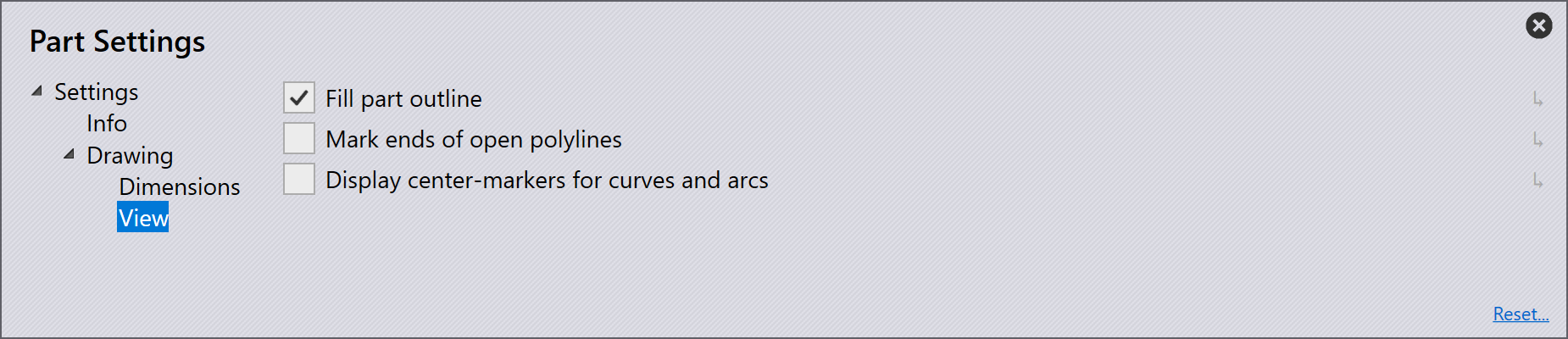
View settings

Fill part outline - Select this checkbox to fill the part outline in the view.

Mark ends of open polylines - Select this checkbox to display markers at the ends of open polylines.

Display center-markers for curves and arcs - Select this checkbox to display center markers for curves and arcs.

Contents

  • Part settings
  • Info - Basic settings
  • Info - Material settings
  • Dimensions
  • View
Bend cell Cut CAM

      Copyright © 2026 TRUMPF Metamation. All rights reserved.

    Compiled by Bento