Flux Reference Manual

  • Welcome to Flux
  • Introduction
    • Installing the software
    • The user interface
    • Part workflow
  • CAD
    • 2-D Import
      • 2-D Cleanup
    • 3-D Import
      • Import 3D Model
      • Import assembly
      • Form detection
      • Component detection
    • Modifying the geometry
    • Attachments
  • Laser CAM
    • Part workflow
      • Editing panels
        • Laser cut
          • Approach
          • Withdrawal
          • Microjoint
          • Advanced
        • Contour
        • Scrap cut
        • Part
        • Corner treatment
      • Quick-Nest
    • Job workflow
      • Job panel
        • Sheets tab
        • Parts tab
        • Layouts tab
        • Summary tab
      • Edit layout
        • Nesting modes
        • Placement panel
        • Sequencing
        • Slice sheet
    • Bevel cut
      • Open contours
      • Variable bevel
      • Miscellaneous
    • Advanced
      • Finishing rules
      • Edit LTT
      • FlyLine
      • TwinLine
        • Strategy
        • Microjoints
        • Further settings
      • DetectLine
  • Bend CAM
    • Create bend data
    • Bend navigator
    • Edit bend data
      • Edit a bend
      • Edit a tool mount
      • Edit a bend setup
      • Edit the back-gauges
      • Edit angle measurement
      • Bends spreadsheet
      • Changing the sequence
      • Adding setups and stations
    • Advanced
      • Angle measurement
      • Batch process
      • Recompute solution
      • Tonnage check
    • Bending Aids
  • BendMaster CAM
    • Bend navigator
    • Part pickup
      • Pickup from pallet
      • Pickup from dispenser
    • Robotic bending
      • Insertion
      • Bending
      • Extraction
    • Regripping
      • Regrip panel
      • Add regrip
      • Edit regrip
      • Regrip with jaw
      • RG-Stations panel
    • Part deposit
      • Deposit panel
      • Repeat and sequence
      • Add separator sheets
      • Lock part-rest
      • Deposit pattern types
    • Advanced
      • Waypoints
      • Cell configuration
      • Custom Cell Components
      • Gripper database
        • Create a gripper
        • Import gripper from DXF
        • Import Suction Cup
  • FlexCell CAM
    • Bend navigator
    • Part pickup
      • Pickup from pallet
      • Centering table
    • Robotic bending
      • Insertion
      • Bending
      • Extraction
      • Advanced
    • Regripping
      • Regrip panel
      • Add/Remove regrip
      • Gripper Panel
      • RG-Stations panel
    • Part deposit
      • Deposit panel
      • Deposit Tabs
    • Advanced
      • Waypoints
      • Cell configuration
      • Gripper database
        • Create a gripper
        • Import gripper from DXF
    • Troubleshooting
  • Fold CAM
    • Create fold data
    • The Fold view
    • Editing Fold data
      • Edit a bend
      • Edit a side/section
      • Change the sequence
      • Edit the blank-holders
      • Edit the gauging
      • Edit the blades
      • Edit the loading
      • Edit the unloading
    • Tool inventory
    • Advanced
      • Custom air-gap tables
      • Manual bend completion
      • Required flange length
  • Settings
    • Drawing
      • Layers
      • Dimensions
      • View
    • Bend CAM
      • Machine defaults
      • Bend outputs
      • Bend view
      • Bend cell
    • Cut CAM
      • Layout
        • Nest settings
        • Sheet
        • Sheet handling
        • Skeleton cuts
        • Work support
      • Laser CAM
        • Sequence
      • Cut outputs
      • Cut view
    • Panel bending
      • Defaults
      • ZBW carriers
      • Outputs
    • Reports
      • Item defaults
    • Import/Export
    • Environment
  • Database
    • Materials
    • Machines
    • Bend tools
    • Bend deductions
    • Bend grippers
    • Forms and Components
  • Reports
    • Report designer
    • Fields, pictures and tables
    • Bands (sub-reports)
    • Labels, bitmaps and shapes
  • Appendix
    • Supported 3D formats
    • Separator sheet DXF
    • Bend tool DXF
    • The Adapt Geometry feature
Laser CAM
/
Job workflow
/
Edit layout
/
Placement panel

Placement panel

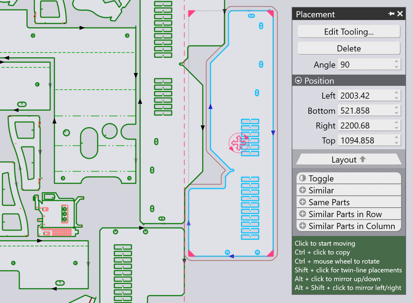
A part that has been added (or any existing part on the layout) can be moved, rotated or repeated with the Placement Panel, which appears when you click on the part:
Placement Panel

  • The Left, Bottom, Right and Top settings are the limits of the bounding box of the part, and these can be used to position the part precisely.

  • You can also just click on the red circular handle at the center of the part and start dragging it to position it on the sheet. As you drag the part around, Flux will add snap guidelines to help you position the part with a precise gap (bridge width) to the adjacent parts. While the part is being placed, an outline is also drawn around the part, offset from the actual part contour by the bridge width.

  • The Angle setting can be used to rotate the part so other orientations can be tried out. When you are dragging the part with its drag handle, you can also hold down the Ctrl key and rotate the mouse-wheel to rotate the part interactively.

  • Use Ctrl+Click to make a copy of the part and then start dragging that copy.

  • Use Alt+Click to mirror the part vertically, and Alt+Shift+Click to mirror the part horizontally.

  • There are several Selectors at the bottom of this panel:

    • Click Toggle to deselect the selected parts, and select everything else.

    • Click Similar to select all copies of the same part at the same angle.

    • Click Same Parts to select all copies of the same part (regardless of rotation angle).

    • Click Similar Parts in Row to select all parts at the same angle and at the same horizontal position.

    • Click Similar Parts in Column to select all parts at the same angle and at the same vertical position.

TwinLine (common-line) placement

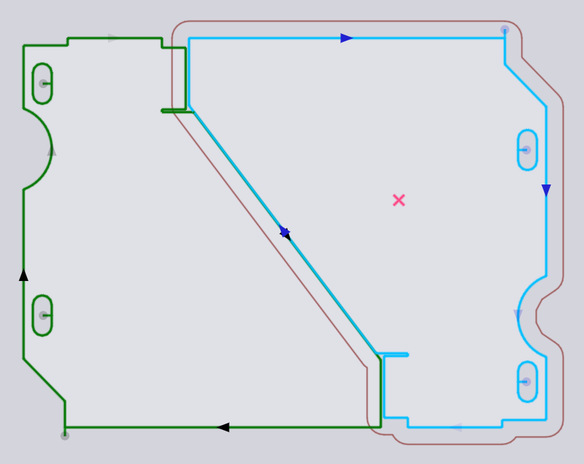
Using Shift+Click to start dragging a part will put the placement into twin-line mode - when you drag two parallel edges close together, Flux will snap them together with precisely one kerf width distance between them, so they can both be cut as a common line. Here’s an example of such a snap happening as we drag a part with Shift+Click:
TwinLine

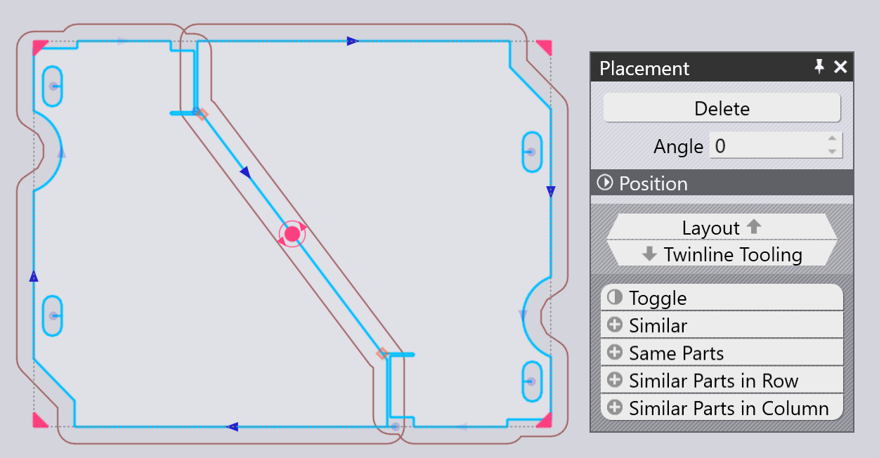
When the mouse is released, the two parts form a single twin-lined group where the shared line is cut only once (you can see that there is only a single cut line arrow at the diagonal line in the middle).
TwinLine

Repeating and grouping parts

Repeat 1

You can select a part, and then use the four handles at the corners of the bounding box to repeat the part. This can be done even with a group of parts that are selected. Here is an example where we start with two adjacent parts selected, and click on the corner handle to start dragging it out:
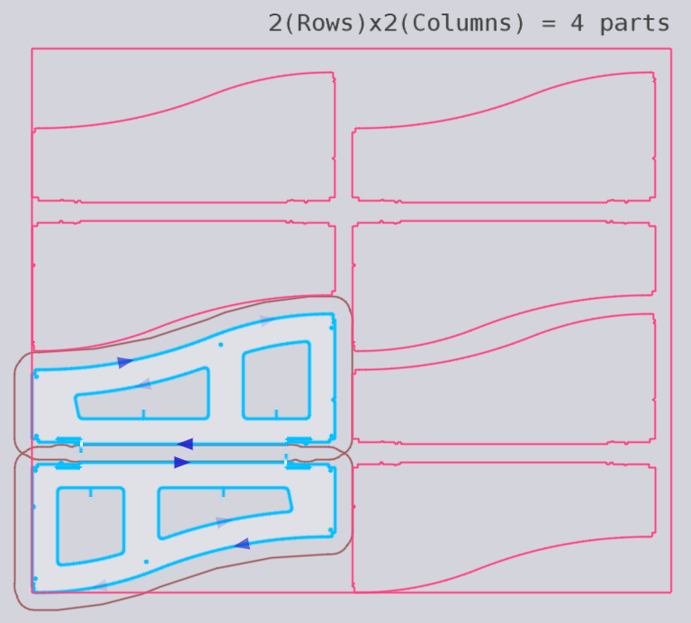
Repeat 2

When you have the required number of rows and columns, you can click to insert the repeated parts:
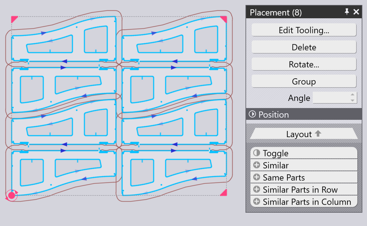
Repeat 3

Repeating with TwinLine

If you start with a single part, or a twin-lined unit of multiple parts, you can hold down Shift key while dragging out the corner to do a twin-line repeat:
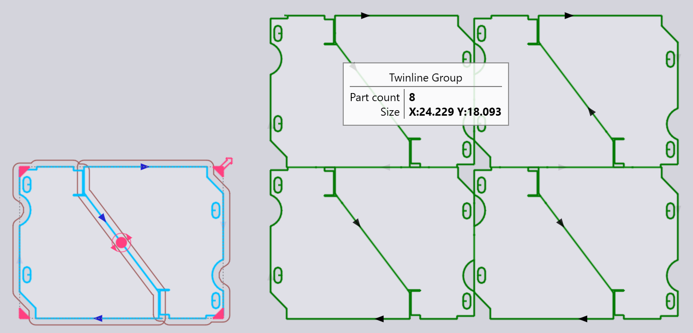
Repeat Twinline

Stretching a group of parts

You can spread out selected parts horizontally or vertically in the empty space left after nesting. The positions of unselected parts remain unchanged. To do this, first click one of the rectangular handles on the bounding box in the direction you want to spread out the parts, and then drag it to the desired position.
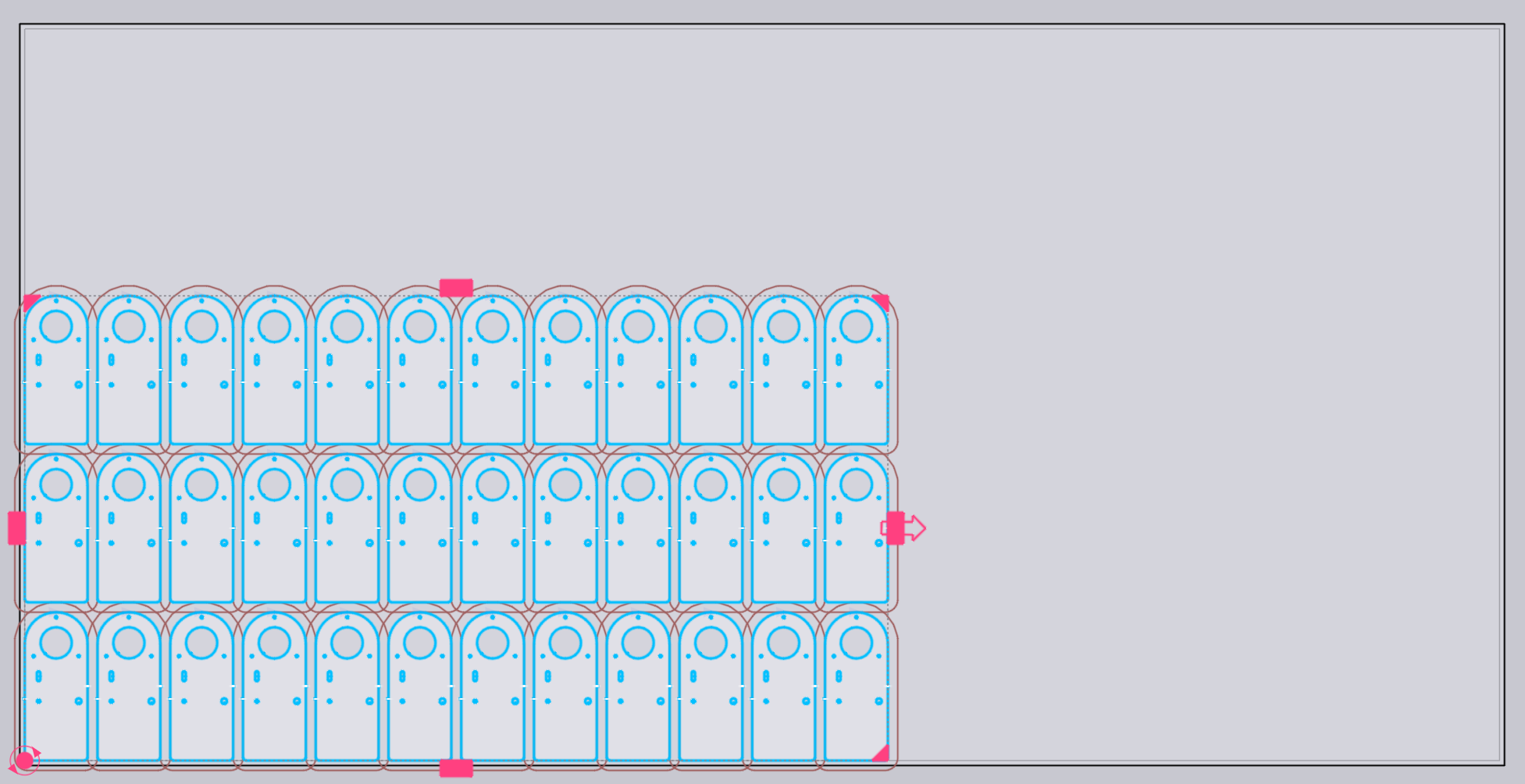
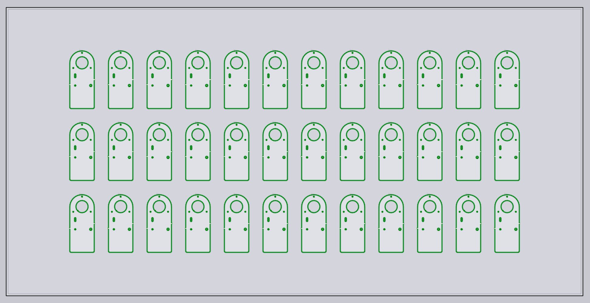
StretchParts1

StretchParts2

Increasing the spacing between parts improves process safety and helps prevent the laser head from colliding with already cut parts.

Grouping

Whenever you have multiple parts selected you can click on the Group button to group them together as a unit. Then, all operations such as move, rotate, mirror and repeat will work on this Group. When a group is selected, you can click Ungroup to break apart this grouping and treat them as individual parts again.

Edit part tooling

The Edit Tooling button of the Placement panel can be used to adjust the laser cut tooling of one or more selected parts directly in the context of the layout. First, select a group of similar parts that you want to edit the tooling for:
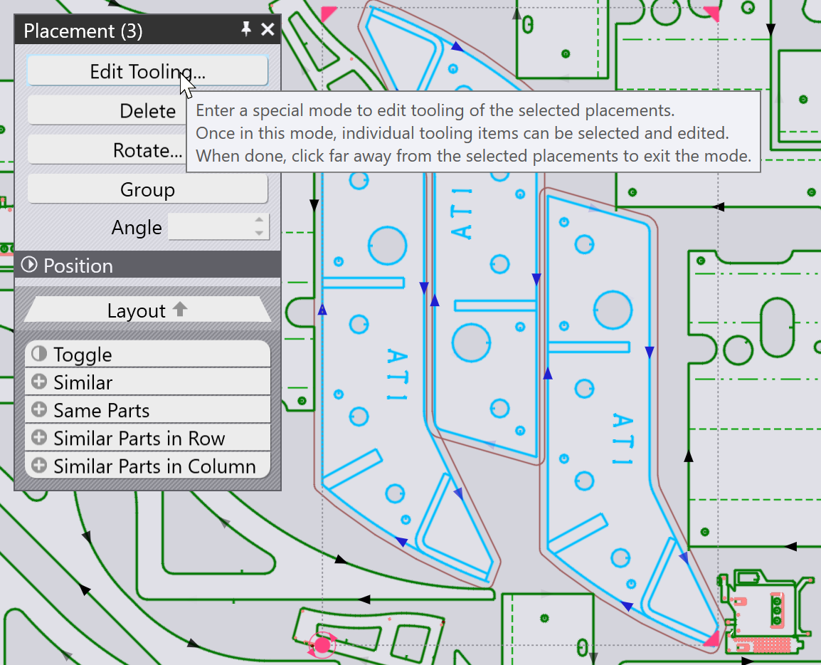
Edit Tooling

All other parts are grayed out, Flux zooms in on the selected parts, and you can then edit the tooling of the part. In this example, let us assume we want to add a Scrap cutting operation on one of the circular holes to slice up that slug:
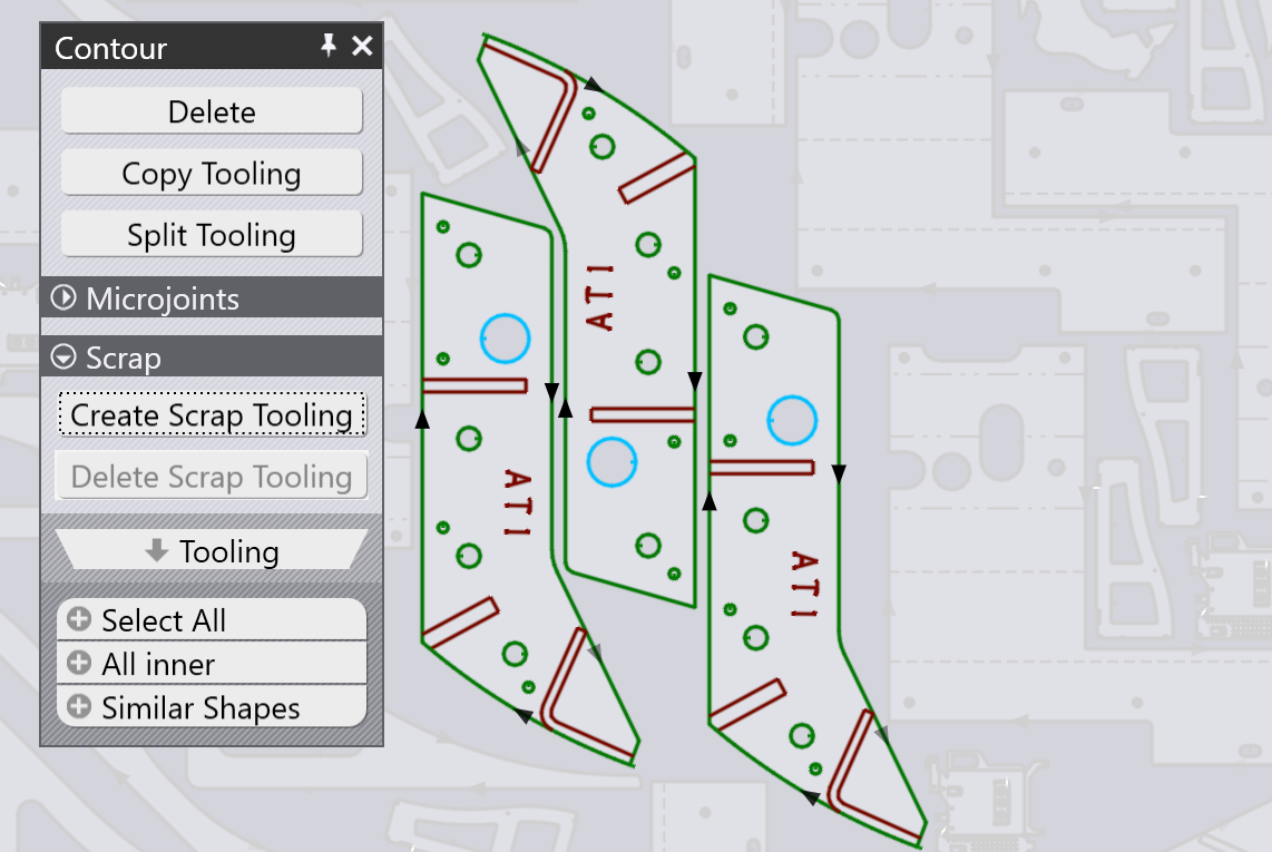
Before Scrap Cut

If you do an edit (like adding the Scrap Cutting), you can see that the edit is applied across all the selected parts. Clicking somewhere away from the group of parts being edited restores back to the full layout. You can see that the three selected parts have the scrap cut tooling added to them.
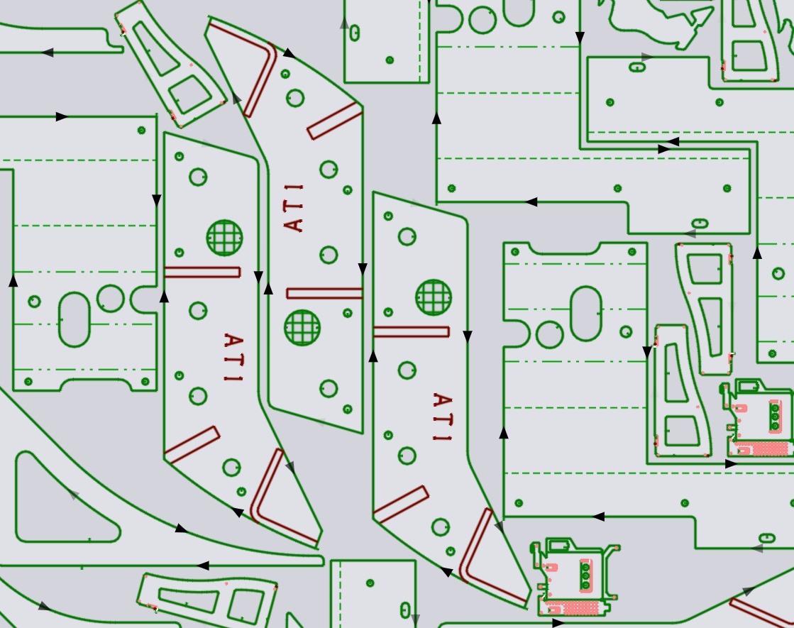
After Scrap Cut

Contents

  • TwinLine (common-line) placement
  • Repeating and grouping parts
  • Repeating with TwinLine
  • Stretching a group of parts
  • Grouping
  • Edit part tooling
Nesting modes Sequencing

      Copyright © 2025 TRUMPF Metamation. All rights reserved.

    Compiled by Bento