
The user interface
Flux uses an innovative user interface design, code-named Clarity. When you are working in Flux, you are presented with an uncluttered, minimalist view.
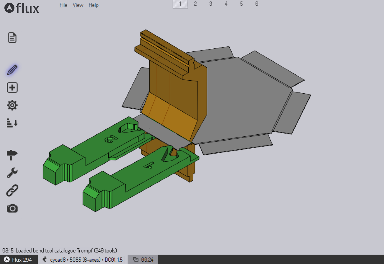
In the Flux interface, you will not find:
-
Many rows of stacked icons, with only a small number being relevant to the current context.
-
Deep menu structures with dozens of menus.
-
User-interface ribbons take up a lot of space on the top of the screen.
Instead, the Clarity interface works on the principle of Select, then Operate.
-
Select things by clicking on them.
-
A Clarity Panel pops-up, containing various Settings and Operations for the selected thing.
-
The Panel often contains some controls for Extend the selection by selecting other similar things.
-
The Panel often also contains controls for Navigating among the various things you are working with.
These user-interface principles are consistent across every working mode of Flux. Whether you are cleaning up a 3D model, arranging parts on a nested sheet, or editing press brake tooling, you will use the same set of key concepts. To make these abstract ideas more concrete, let us take a small excursion and see the Clarity interface in action (we will take examples from the Flux report editor and from Flux Bend to illustrate).
A guided tour
This is a quick tour of how the Clarity interface works. There are just a handful of simple concepts that are repeated everywhere in Flux, and understanding these concepts will mean that most of Flux can be used without much reading or training. In other words, if you read this section, you could skip reading the rest of the Flux user guide!
A sample report
You can learn more about creating and editing report templates in a later section. For now, let us introduce some report terminology so we can use this to illustrate concepts of the Clarity interface.
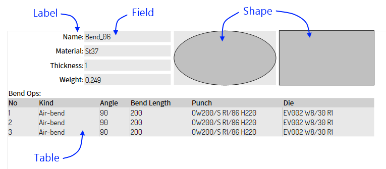
The image above shows some of the types of entities that could be placed in a report.
-
A Label is a simple piece of text; you can set various properties like the font, text-alignment, and the color.
-
A Field displays some actual data picked up from the underlying Part.
-
A Shape is some simple geometry (like an ellipse, rectangle, or line) that can be used to add back-drops, highlights, or dividers in a report.
-
A Table displays data from the underlying Part that has a tabular form (like a spreadsheet of information). In this example, we can see a list of bend operations in this part, and some attributes are displayed for each of them.
With this basic background about report entities, we can now begin exploring the Clarity interface.
Principle: Click on something to edit it
Click on a Field, and a Clarity Panel is displayed (let’s just call this a Panel in this discussion). Here’s an annotated diagram of how it could look:
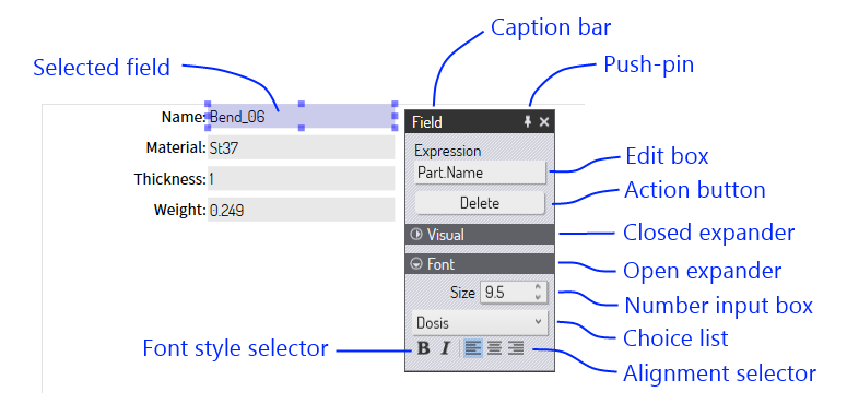
Clicking on a field selects it and displays a Panel for editing it. Here are some of the elements we see in this panel:
-
The caption bar can be used to re-position the panel (you can click anywhere on the background of the panel and drag it). If you set the pushpin in, then panels always open at that location on the screen. Else, panels open close to the location of the mouse cursor.
-
Edit boxes, number input boxes, choice lists, font and alignment selectors are all various ways in which the settings of the Field are viewed and edited.
-
Action buttons are how various operations are performed on the selected object. In this case, one could delete the field from the report by clicking on the Delete button.
-
Some Panels may contain many elements. To reduce clutter, the panels are divided into sections, using Expanders. In the image above, you can see the Visual expander is closed (hiding all the settings in that section), while the Font expander is open. You can click anywhere on the expander to open or close a section.
Principle: Select multiple things and edit them together
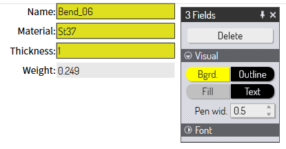
You can select additional entities by holding down the Shift key when you click on them. When multiple entities are selected, a Panel is displayed that allows you to edit the settings of all of them at the same time.
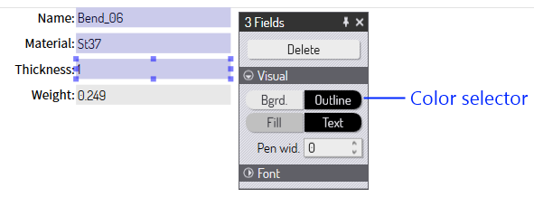
In the image above, we have 3 fields that we selected using the Shift+Click mechanism. The panel that is displayed allows us to edit the settings of all these three fields at the same time. (Here we have the Visual expander open, and the Font expander closed). After editing the Bgrd. color and the Pen-wid. settings, here’s how the report looks:
The changes we made are applied to all the selected items. In this multiple-edit scenario, note that the Expression setting is not displayed; this is one of the settings that we are unlikely to want to edit together for a set of fields (we would not really want 3 fields displaying the same value from the Part). Settings which would usually have distinct values for each entity are not displayed in such group-editing panels.
Principle: You can edit entities of different types together
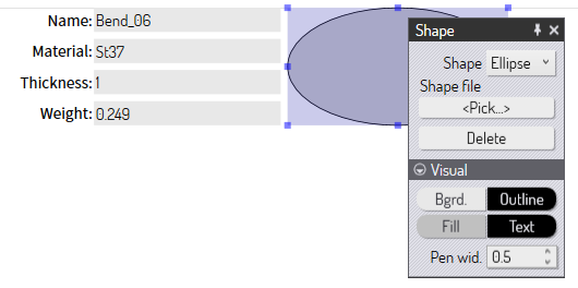
In the example above, we selected three entities of the same type. What happens if we select entities of different types? Let us see. First, here is how the panel for a Shape entity looks:
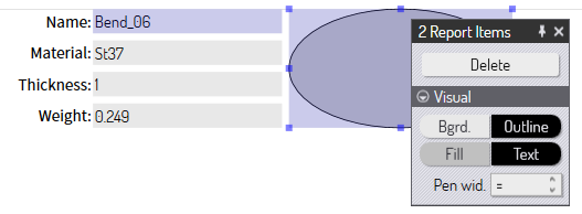
If we select a Field and a Shape at the same time, this is the panel that is displayed:
-
The caption bar now reads 2 Report Items since we are editing report items, but not of the same type.
-
Only the common settings between Field and Shape are displayed (in this case, these are just the settings in the Visual section).
Principle: Multiple selection may provide additional operations
In addition to the common subset of settings and operations available on multiple objects, multiple selection may sometimes present new operations or settings that are not available on individual objects. Let us take an example from the bending view to illustrate this. In the bend view, clicking on a bend displays a panel to edit the settings of the bend and perform some operations on it:
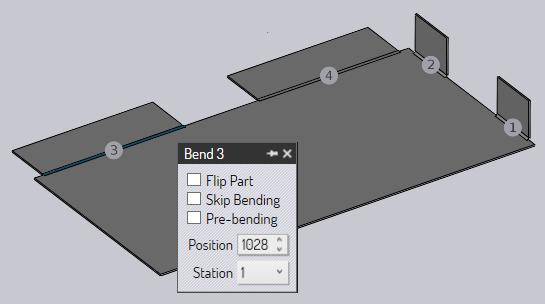
The image above shows the panel for bend 3. Let us now hold down Shift and select bend 4 as well. The panel that is now displayed looks like this:
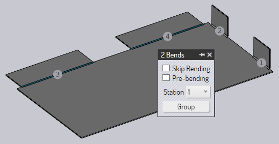
There are some settings that we can edit in common (the skip bending setting or the station number setting). However, we see a new button here called Group. Since two bends are selected, and these are collinear, they could be grouped into a single bend operation. This is detected automatically, and this new Group button is displayed; this operation is not available when just a single bend is selected. Clicking on that button groups the two bends together, as you can see in the image below.
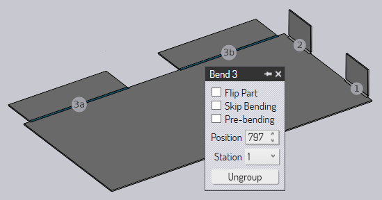
Now, there are only 3 bend operations in this part. Also, bend 3 is now a grouped bend and you see a new button appear: Ungroup.
Principle: Use the Selection sub-panel to modify the selection
A Clarity panel will often have a Selection sub-panel near the bottom. This panel provides some buttons to modify the selection in various ways. Usually, there are buttons to select more objects that are similar in some way or the other. For example, some ways to expand the selection would be:
-
Select all Fields in a report.
-
Select all polylines in the same layer.
-
Select all punch-hits in a part that use the same punch tool.
-
Select all bends that use the same setup.
Here is an example from the report editor of a selection panel being displayed when we click on a Field in a report:
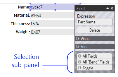
The selection sub-panel has a distinctive patterned background and rounded buttons. In this example, you can see buttons to select All Fields, select All Bend Fields (fields related to bend CAM data), and Toggle (the current selection set).
The actual list of selection buttons displayed in this sub-panel will vary depending on the context. You will find that most common scenarios are handled very conveniently by these selection buttons.
Principle: Use the Navigation sub-panel to walk through the entity tree
The set of entities in a part, report or layout often have a hierarchical structure. We call this the Entity Tree. The structure is typically represented like an upside-down tree, with the 'parent' object at the top and children below it. Here’s an example of an entity tree in a report.
-
A report could have multiple items within it. Some of these items could be Tables.
-
A Table in a report could have multiple Columns in it.
Thus, there are 3 levels in this tree, and a graphical representation of this tree could be as follows:
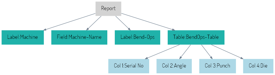
This report has 2 Labels, 1 Field and 1 Table. The Table has 4 columns. When we click on the table, we see a panel like this:
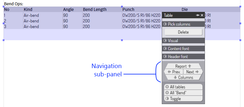
The navigation panel provides directional navigation buttons to walk through the entity tree. Like the selection panel, the navigation sub-panel has a distinctive textured background, and appears at the bottom of the panel, but just above the selection sub-panel.
The Prev. and Next buttons move among items at the same level of the entity tree. Thus, clicking these buttons would select the other items in the report, such as the Label or the Field items in the report.
Clicking the Report would move up from the table to the parent - the Report itself. The panel that is displayed when you click on the Report button shows some settings related to the report itself, such as the paper size and the margins:
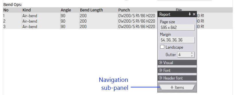
Now we are editing the report; we are at the root of the entity tree. There is no direction to go but down, and thus the navigation sub-panel has just one button ( Items) to go down to the list of items. Clicking this selects the table again.
From the table, the down navigation Columns button moves us down one level and puts us in column-editing mode. This is what happens when we click the Columns navigation button from the table panel:
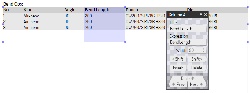
The settings for the selected column in the table are displayed. Clicking the Prev. and Next buttons now moves the selection between the columns in the table, since that is the level in the tree we are working with. There is no down navigation button, since this is the lowest level in the tree. The Table button moves up one level, and we are back to editing the entire table.
Summary
-
Click on something to edit it.
-
Select multiple things, and you can then edit them together.
-
You can also edit entities of different types together.
-
Multiple-selection may provide additional settings and operations.
-
Use the Selection sub-panel to intelligently modify the selection.
-
Use the Navigation sub-panel to walk through the entity tree.