Flux Reference Manual

  • Welcome to Flux
  • Introduction
    • Installing the software
    • The user interface
    • Part workflow
  • CAD
    • 2-D Import
      • 2-D Cleanup
    • 3-D Import
      • Import 3D Model
      • Import assembly
      • Form detection
      • Component detection
    • Modifying the geometry
    • Attachments
  • Laser CAM
    • Part workflow
      • Editing panels
        • Laser cut
          • Approach
          • Withdrawal
          • Microjoint
          • Advanced
        • Contour
        • Scrap cut
        • Part
        • Corner treatment
      • Quick-Nest
    • Job workflow
      • Job panel
        • Sheets tab
        • Parts tab
        • Layouts tab
        • Summary tab
      • Edit layout
        • Nesting modes
        • Placement panel
        • Sequencing
        • Slice sheet
    • Bevel cut
      • Open contours
      • Variable bevel
      • Miscellaneous
    • Advanced
      • Finishing rules
      • Edit LTT
      • FlyLine
      • TwinLine
        • Strategy
        • Microjoints
        • Further settings
      • DetectLine
  • Bend CAM
    • Create bend data
    • Bend navigator
    • Edit bend data
      • Edit a bend
      • Edit a tool mount
      • Edit a bend setup
      • Edit the back-gauges
      • Edit angle measurement
      • Bends spreadsheet
      • Changing the sequence
      • Adding setups and stations
    • Advanced
      • Angle measurement
      • Batch process
      • Recompute solution
      • Tonnage check
    • Bending Aids
  • BendMaster CAM
    • Bend navigator
    • Part pickup
      • Pickup from pallet
      • Pickup from dispenser
    • Robotic bending
      • Insertion
      • Bending
      • Extraction
    • Regripping
      • Regrip panel
      • Add regrip
      • Edit regrip
      • Regrip with jaw
      • RG-Stations panel
    • Part deposit
      • Deposit panel
      • Repeat and sequence
      • Add separator sheets
      • Lock part-rest
      • Deposit pattern types
    • Advanced
      • Waypoints
      • Cell configuration
      • Custom Cell Components
      • Gripper database
        • Create a gripper
        • Import gripper from DXF
        • Import Suction Cup
  • FlexCell CAM
    • Bend navigator
    • Part pickup
      • Pickup from pallet
      • Centering table
    • Robotic bending
      • Insertion
      • Bending
      • Extraction
      • Advanced
    • Regripping
      • Regrip panel
      • Add/Remove regrip
      • Gripper Panel
      • RG-Stations panel
    • Part deposit
      • Deposit panel
      • Deposit Tabs
    • Advanced
      • Waypoints
      • Cell configuration
      • Gripper database
        • Create a gripper
        • Import gripper from DXF
    • Troubleshooting
  • Fold CAM
    • Create fold data
    • The Fold view
    • Editing Fold data
      • Edit a bend
      • Edit a side/section
      • Change the sequence
      • Edit the blank-holders
      • Edit the gauging
      • Edit the blades
      • Edit the loading
      • Edit the unloading
    • Tool inventory
    • Advanced
      • Custom air-gap tables
      • Manual bend completion
      • Required flange length
  • Settings
    • Drawing
      • Layers
      • Dimensions
      • View
    • Bend CAM
      • Machine defaults
      • Bend outputs
      • Bend view
      • Bend cell
    • Cut CAM
      • Layout
        • Nest settings
        • Sheet
        • Sheet handling
        • Skeleton cuts
        • Work support
      • Laser CAM
        • Sequence
      • Cut outputs
      • Cut view
    • Panel bending
      • Defaults
      • ZBW carriers
      • Outputs
    • Reports
      • Item defaults
    • Import/Export
    • Environment
  • Database
    • Materials
    • Machines
    • Bend tools
    • Bend deductions
    • Bend grippers
    • Forms and Components
  • Reports
    • Report designer
    • Fields, pictures and tables
    • Bands (sub-reports)
    • Labels, bitmaps and shapes
  • Appendix
    • Supported 3D formats
    • Separator sheet DXF
    • Bend tool DXF
    • The Adapt Geometry feature
Bend CAM
/
Edit bend data
/
Bends spreadsheet

Bends spreadsheet

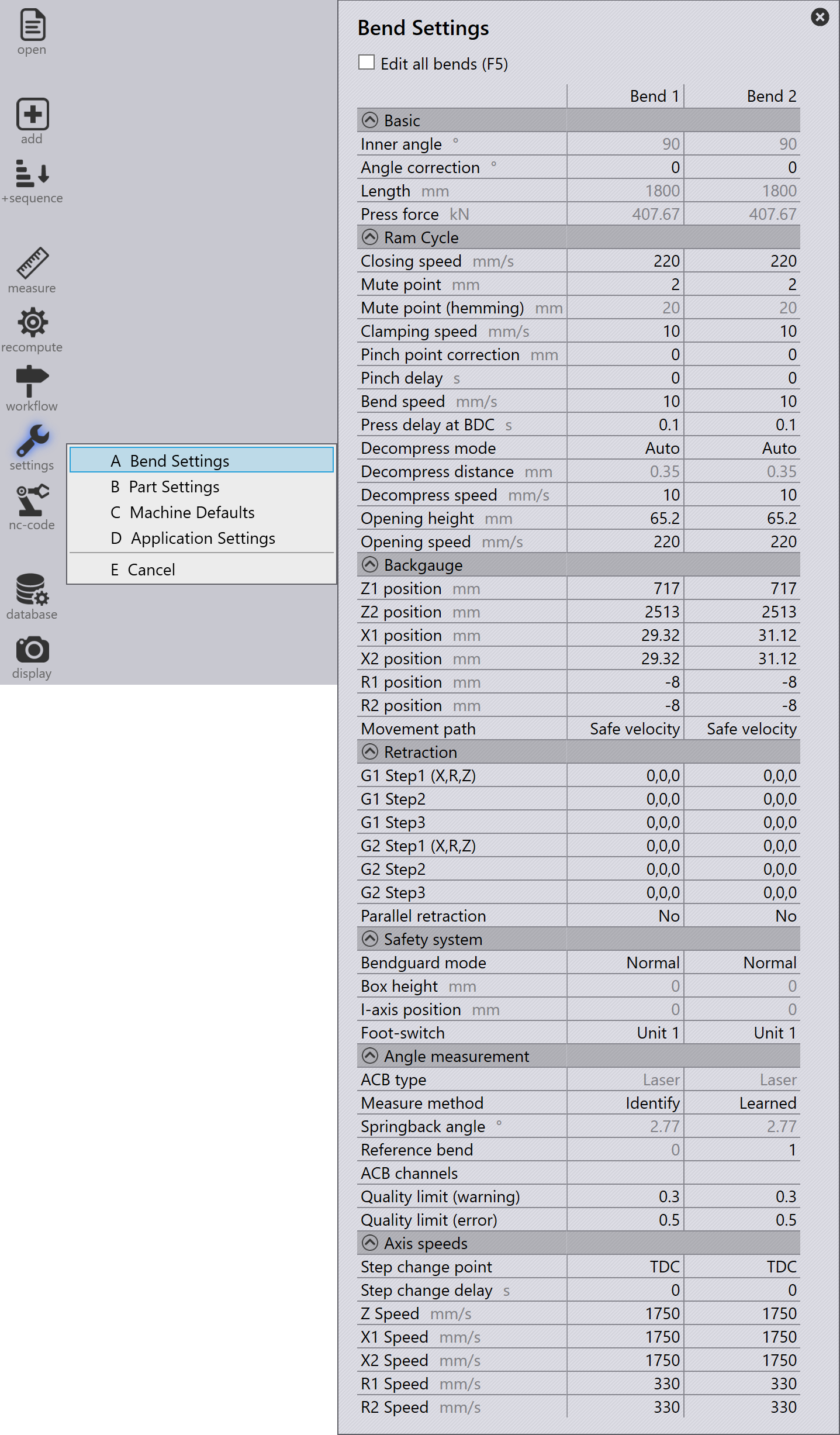
You can do a detailed editing of all settings for all bends by opening the Bend Settings spreadsheet. To access this spreadsheet select the settings icon from the command bar, and select Bend Settings (or use the shortcut key sequence T, A).

The number of bend column in the Bend Settings depends on the number of bends in the bend part.
Bend Settings
Table 1. Basic

Field

Description

Inner angle

The inner angle of bending.

Length

Total bend length.

Press force

Computed press force.

Table 2. Ram Cycle
Field Description

Closing speed

The speed of the beam up to the mute point.

Mute point

At the mute point, the max speed ("Rapid down") is automatically switched over to the reduced speed ("Clamping"). The mute point is above the top edge of the lower tool. "Mute distance 1" programmed sheet thickness = distance between the tip of the upper tool and the upper edge of the lower tool.

Clamping speed

The speed of the beam between the mute point and the clamping point.

Clamping point correction

Adjust the value to compensate for variations in sheet thickness.

Pinch delay

The delay is mostly required by automated machines. During the waiting time, the beam will stop at the clamping point.

Bend speed

The speed of the beam during bending.

Press delay at BDC

The beam will remain at the lower dead point for this duration.

Decompress distance

With the decompression path, the tension in the machine’s frame is released in a controlled fashion after a bend, as it is under maximum tension at the lower dead point (LDP). The decompression path moves the beam upwards at a slow speed.

Decompress speed

Speed of the beam along the decompression path (decompression).

Opening height

The beam opening is the measure by which the beam moves upward after a bending operation.
Positive value: Press beam is positioned above the mute point.
Negative value: Press beam is positioned below the mute point.

Opening speed

Speed of the beam after the decompression path (decompression).

Table 3. Backgauge
Field Description

Retract direction

Here you select in which direction the back gauge is to be withdrawn.

Retraction 1 and Retraction 2

Distances by which the gauges 1 and 2 move away from the gauging position once the part is clamped.

Z1 position

Z position of gauge 1

Z2 position

Z position of gauge 2

X1 position

X position of gauge 1

X2 position

X position of gauge 2

R1 position

Z position of gauge 1

R2 position

Z position of gauge 2

Table 4. Axis speeds

Z Speed

Gauge speeds in Z

X1 Speed

Gauge 1 speed in X

X2 Speed

Gauge 2 speed in X

R1 Speed

Gauge 1 speed in R

R2 Speed

Gauge 2 speed in R

Edit angle measurement Changing the sequence

      Copyright © 2025 TRUMPF Metamation. All rights reserved.

    Compiled by Bento