
Sequencing
When a laser part is being tooled up (see Part Workflow), Flux computes a sequence in which the tooling for the part should be cut. At a basic level, holes in the part need to be cut out first, before the outer contour is cut.
When a layout is being composed either by the nesting engine, or interactively by adding or editing parts in a layout, Flux computes a sequence in which all the tooling across all the parts in the layout are processed. A common option is that the tooling is processed part-by-part (the inner tooling and the outer contour of one part are cut before moving on to the next part). There are other sequencing options as well, and these can be controlled using the Laser Sequence settings.
This automatically computed sequence (either for a part or for a layout) can be inspected or changed using the Sequence navigator.
Sequence navigator
The Sequence navigator appears along the right edge of the Flux window when we are working with a laser part or layout. You can toggle it open or closed using the Z key.
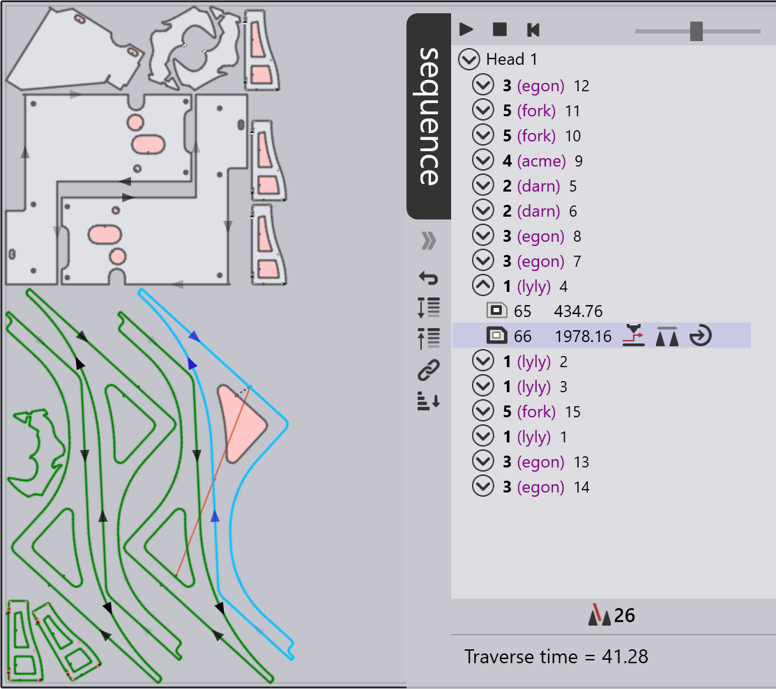
In this image, the sequence navigator is being used to edit the sequence of a layout. Here, a part-by-part sequence has been computed and you can see the order in which the parts are going to be processed.
You can open one of these part nodes (as the 1 (lyly) 4 node has been opened in the image), and then see the individual laser cuts within that part. The laser cut you have clicked on (tagged with sequence number 66 in the image) is highlighted in blue. All the tooling that has been cut before this is shown filled in white or pink (pink fills indicate that the tooling is unstable and may fall through the slats).
The traverse line from the previous tooling to the selected one, as well as the traverse line from this tooling to the next one, are both displayed for context.
Reordering tooling
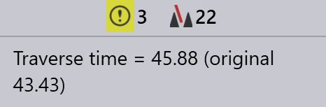
You can click on a node representing a full part, or a node representing an individual laser cut and drag it up or down to reorder the tooling. As you do so, the Traverse time is computed and updated immediately, and displayed at the bottom of the sequence navigator. You can revert back to the original sequence by clicking on the Revert all changes icon in the sequence navigator.
You can also use the Interactive sequence button to change the order of the tooling:
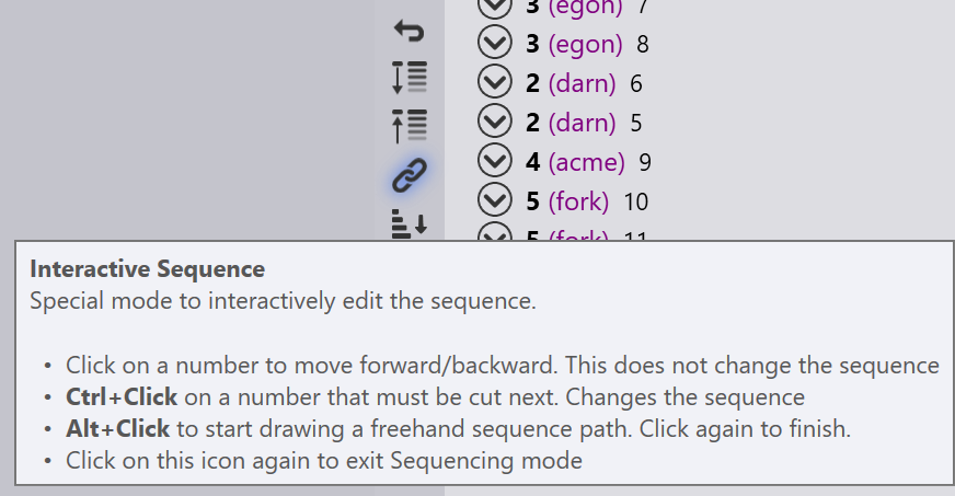
To set up a sequence, you just Ctrl+Click on the numbers in the order in which you want to process them. Often, you want to change only some localized part of the sequence, and that is also possible. In the illustration below, we want to keep the sequence until item 8, and then change only the part after that.
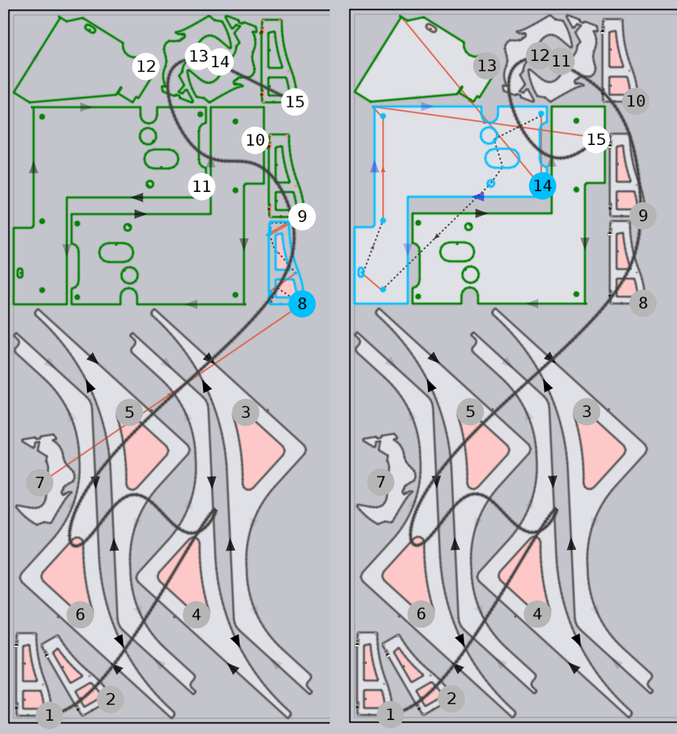
To do that easily, you can first click on the 8 (without holding down Ctrl), and the sequence up to that point is accepted (shown as gray circles). Then you can Ctrl+Click on subsequent numbers to add them to the sequence in that order. You can see a modified sequence being set by the subsequent clicks above.
You can also just draw a rough line indicating the approximate flow along which you would like the parts to be cut. To do this, Alt+Click on the sheet and drag the mouse to create a curve (shown in the image below left).
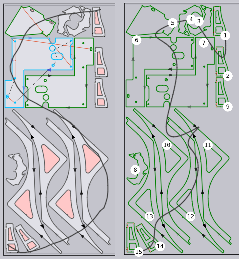
After you are done drawing the sequence curve, click once more, and the parts will then be sequenced to follow the trace you have drawn (as shown in the image above right).
Sequence icons
The Warnings indicator at the bottom appears if there are any warnings. Click on this indicator repeatedly to highlight each of the warnings.
The tilting contours indicator shows the contours that could possibly fall through the slats. Click on this indicator repeatedly to highlight all the contours that might tilt.
Here are the other symbols that appear in the sequence navigator. They are used to adjust the hierarchical view of tooling items, simulate the sequence and adjust it in other ways.
Icon |
Meaning |
|
Play the simulation. |
|
Stop the simulation at its current position. |
|
Rewind the simulation back to the start. |
|
Collapse the sequence navigator to the right. |
|
Expand the sequence navigator to the left. |
|
Revert all changes made to the sequence, and reset it back to the original. |
|
This is a special mode to interactively edit the sequence. Click on the icon
to activate it. |
|
Expand all tooling sequences for all parts. This allows easy viewing of what tooling is being carried out. For example, marking or inner contour. |
|
Collapse all the open tooling sequences. |
|
When link option is selected, changes made to the sequence or routing done at one place are automatically repeated at other identical places. This is best to be turned on if it is preferable for changes to be done within a part to be automatically copied to other instances of the same part with identical tooling and sequence. |
|
Laser head down. |
|
Laser head up with ping-pong laser motion, also synchronous Z movement. When active, the traverse path is marked in violet on the sheet. This will be turned off in certain cases to reduce the danger of tilting and collisions. |
|
Head up without ping-pong. Flux chooses this motion when head up with ping-pong might lead to tilting incidents. |
|
Traverse to next cut happens with assist gas switched on. |
|
Traverse to next cut happens with assist gas switched off. |
|
Part falls through the slats. |
|
Part remains on slats. |
|
Part tilts and sticks up between the slats. |
|
Pierce only. Applies when Laser processing sequence is set to a condition where piercing for all contours is done first (i.e. Pierce then Cut, Pierce > Mark > Cut or Mark > Pierce > Cut). |
|
Inner contour. |
|
Outer contour. |


