
Flux Reference Manual

  • Welcome to Flux
  • Introduction
    • Installing the software
    • The user interface
    • Part workflow
  • CAD
    • 2-D Import
      • 2-D Cleanup
    • 3-D Import
      • Import 3D Model
      • Import assembly
      • Form detection
      • Component detection
    • Modifying the geometry
    • Attachments
  • Laser CAM
    • Part workflow
      • Editing panels
        • Laser cut
          • Approach
          • Withdrawal
          • Microjoint
          • Advanced
        • Contour
        • Scrap cut
        • Part
        • Corner treatment
      • Quick-Nest
    • Job workflow
      • Job panel
        • Sheets tab
        • Parts tab
        • Layouts tab
        • Summary tab
      • Edit layout
        • Nesting modes
        • Placement panel
        • Sequencing
        • Slice sheet
    • Bevel cut
      • Open contours
      • Variable bevel
      • Miscellaneous
    • Advanced
      • Finishing rules
      • Edit LTT
      • FlyLine
      • TwinLine
        • Strategy
        • Microjoints
        • Further settings
      • DetectLine
  • Bend CAM
    • Create bend data
    • Bend navigator
    • Edit bend data
      • Edit a bend
      • Edit a tool mount
      • Edit a bend setup
      • Edit the back-gauges
      • Edit angle measurement
      • Bends spreadsheet
      • Changing the sequence
      • Adding setups and stations
    • Advanced
      • Angle measurement
      • Batch process
      • Recompute solution
      • Tonnage check
    • Bending Aids
  • BendMaster CAM
    • Bend navigator
    • Part pickup
      • Pickup from pallet
      • Pickup from dispenser
    • Robotic bending
      • Insertion
      • Bending
      • Extraction
    • Regripping
      • Regrip panel
      • Add regrip
      • Edit regrip
      • Regrip with jaw
      • RG-Stations panel
    • Part deposit
      • Deposit panel
      • Repeat and sequence
      • Add separator sheets
      • Lock part-rest
      • Deposit pattern types
    • Advanced
      • Waypoints
      • Cell configuration
      • Custom Cell Components
      • Gripper database
        • Create a gripper
        • Import gripper from DXF
        • Import Suction Cup
  • FlexCell CAM
    • Bend navigator
    • Part pickup
      • Pickup from pallet
      • Centering table
    • Robotic bending
      • Insertion
      • Bending
      • Extraction
      • Advanced
    • Regripping
      • Regrip panel
      • Add/Remove regrip
      • Gripper Panel
      • RG-Stations panel
    • Part deposit
      • Deposit panel
      • Deposit Tabs
    • Advanced
      • Waypoints
      • Cell configuration
      • Gripper database
        • Create a gripper
        • Import gripper from DXF
    • Troubleshooting
  • Fold CAM
    • Create fold data
    • The Fold view
    • Editing Fold data
      • Edit a bend
      • Edit a side/section
      • Change the sequence
      • Edit the blank-holders
      • Edit the gauging
      • Edit the blades
      • Edit the loading
      • Edit the unloading
    • Tool inventory
    • Advanced
      • Custom air-gap tables
      • Manual bend completion
      • Required flange length
  • Settings
    • Drawing
      • Layers
      • Dimensions
      • View
    • Bend CAM
      • Machine defaults
      • Bend outputs
      • Bend view
      • Bend cell
    • Cut CAM
      • Layout
        • Nest settings
        • Sheet
        • Sheet handling
        • Skeleton cuts
        • Work support
      • Laser CAM
        • Sequence
      • Cut outputs
      • Cut view
    • Panel bending
      • Defaults
      • ZBW carriers
      • Outputs
    • Reports
      • Item defaults
    • Import/Export
    • Environment
  • Database
    • Materials
    • Machines
    • Bend tools
    • Bend deductions
    • Bend grippers
    • Forms and Components
  • Reports
    • Report designer
    • Fields, pictures and tables
    • Bands (sub-reports)
    • Labels, bitmaps and shapes
  • Appendix
    • Supported 3D formats
    • Separator sheet DXF
    • Bend tool DXF
    • The Adapt Geometry feature
BendMaster CAM
/
Bend navigator

Bend navigator

Navigator

The Bend Navigator at the top of the screen provides an overview of the complete cycle. Most of the icons and terminology used in the navigator are similar to the ones found in the navigator for manual bending. However, robotic bending introduces extra rows and columns due to its added complexity, which are explained here.

Pickup, regrip and deposit columns

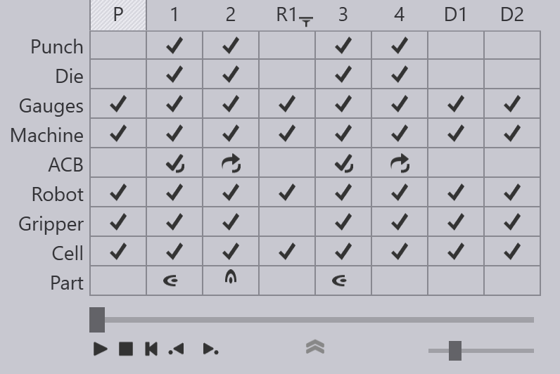
The image above shows the bend navigator displayed for a BendMaster part with four bends. The bends can be seen in the columns tagged 1 to 4, and there are some additional columns displayed.

  • The column marked P represents the part pickup operation. Before bending can start, the BendMaster has to pick up a blank (flat sheet) from a pallet, or from a part dispenser. This column represents this operation. You can click on it to and use the slider to view a simulation of the pickup operation. If there are any collisions or other issues during this pickup, the corresponding rows in this column will light up yellow (for warnings) or red (for errors).

  • The columns marked with tags like R1, R2 represent regrip operations. During pickup, the gripper will pick up the part by gripping it along a particular plane, in a particular orientation. Sometimes, not all the bends in the part can be processed with this same orientation, and the gripper may need to regrip the part to continue. In this example above, the gripper had to pick up the part with a different orientation between bends 2 and 3 using a regrip operation. The R1 column can be used to simulate this regrip operation, or to monitor that operation for collisions or other errors.

  • The columns marked with tags like D1, D2 represent the part deposit operations on the final pallet, conveyor or basket. Each of the deposit columns represents a particular orientation of the part on the deposit stack and there may be several such orientations depending on the deposit pattern being used.

Robot, gripper and cell rows

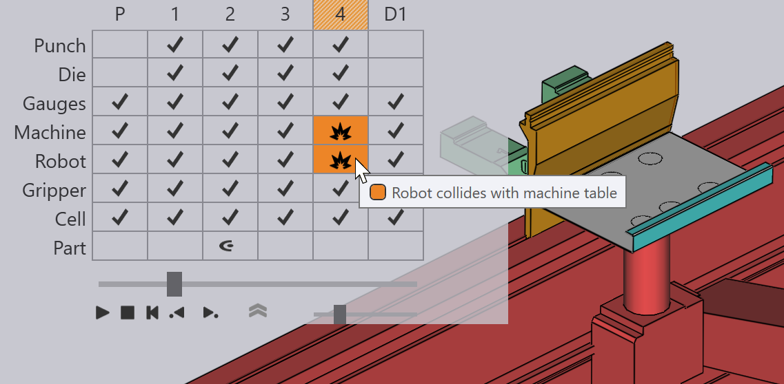
There are new rows added for the Robot, the Gripper and the other Cell components. These rows are used to signal collisions or other errors. For example, a collision between the robot and the machine table is signalled by a red collision icon in both those rows. During the simulation, the colliding components also turn red:
Robot-Table Crash

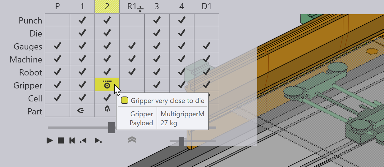
The Gripper row displays collisions or other issues related to the gripper. For example, the image below shows a warning related to the suction gripper:
Gripper Too Close

The Cell row represents the state of other cell components, including:

  • The Pickup and deposit pallets

  • The part dispenser

  • The regrip stations

  • Gripper stations

  • Conveyors

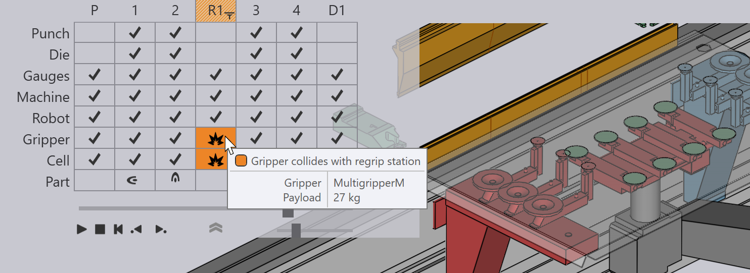
Here is an error icon in the Cell row indicating a collision with the regrip station:
Gripper-Regrip Crash

Shortcut keys

These shortcut keys can help speed up navigation between the different modes and panels in Flux.

Navigator shortcuts

PgUp PgDn

Switch to the previous or next stage in the simulation


Switch to the previous or next phase within the same stage. For example, phases in bending are the steps like part insert, gauge-retract, bend, and beam-open.

Spacebar

Start/stop the simulation

Z

Expand/collapse the navigator panel.

Panel shortcuts (keyboard)

E E

Open the panel for the current stage (bend / pickup / regrip / deposit)

E B

Open the Back-gauge panel for the current bend

E D

Open the Die panel

E G

Open the Gripper panel (to adjust the gripper position for this stage)

E R

Open the Robot Strategy panel for the current bend

E W

Open the Waypoints panel for the current stage

Panel shortcuts (mouse)

Left click twice on navigator header

The first click switches the simulation to that stage. The second click opens the panel for the stage

Left click on the back-gauge

Open the Back-gauge panel for the current bend

Left click on the die

Open the Die panel

Left click on the punch

Open the Punch panel

Left click on the gripper (or robot C axis)

Open the Gripper panel

Left click on the pallet

Open the Pallet panel

Left click on the camera

Open the Camera panel (editing pickup detection images for this part)

Left click on a blank on the pickup pallet

Open the Pickup panel

Left click on a suction cup of a gripper

Open the Suction panel (suction cup settings for this gripper)

Left click on a part on the deposit pallet

Open the Deposit panel

Left click on the X,A or B axes of the robot

Open the Robot Strategy panel for the current bend

Left click on the robot rail

Open the Waypoints panel for the current stage

Left click on the regrip stations

Open the Regrip Stations panel

Contents

  • Pickup, regrip and deposit columns
  • Robot, gripper and cell rows
  • Shortcut keys
BendMaster CAM Part pickup

      Copyright © 2025 TRUMPF Metamation. All rights reserved.

    Compiled by Bento