
Flux Reference Manual

  • Welcome to Flux
  • Introduction
    • Installing the software
    • The user interface
    • Part workflow
  • CAD
    • 2-D Import
      • 2-D Cleanup
    • 3-D Import
      • Import 3D Model
      • Import assembly
      • Form detection
      • Component detection
    • Modifying the geometry
    • Attachments
  • Laser CAM
    • Part workflow
      • Editing panels
        • Laser cut
          • Approach
          • Withdrawal
          • Microjoint
          • Advanced
        • Contour
        • Scrap cut
        • Part
        • Corner treatment
      • Quick-Nest
    • Job workflow
      • Job panel
        • Sheets tab
        • Parts tab
        • Layouts tab
        • Summary tab
      • Edit layout
        • Nesting modes
        • Placement panel
        • Sequencing
        • Slice sheet
    • Bevel cut
      • Open contours
      • Variable bevel
      • Miscellaneous
    • Advanced
      • Finishing rules
      • Edit LTT
      • FlyLine
      • TwinLine
        • Strategy
        • Microjoints
        • Further settings
      • DetectLine
  • Bend CAM
    • Create bend data
    • Bend navigator
    • Edit bend data
      • Edit a bend
      • Edit a tool mount
      • Edit a bend setup
      • Edit the back-gauges
      • Edit angle measurement
      • Bends spreadsheet
      • Changing the sequence
      • Adding setups and stations
    • Advanced
      • Angle measurement
      • Batch process
      • Recompute solution
      • Tonnage check
    • Bending Aids
  • BendMaster CAM
    • Bend navigator
    • Part pickup
      • Pickup from pallet
      • Pickup from dispenser
    • Robotic bending
      • Insertion
      • Bending
      • Extraction
    • Regripping
      • Regrip panel
      • Add regrip
      • Edit regrip
      • Regrip with jaw
      • RG-Stations panel
    • Part deposit
      • Deposit panel
      • Repeat and sequence
      • Add separator sheets
      • Lock part-rest
      • Deposit pattern types
    • Advanced
      • Waypoints
      • Cell configuration
      • Custom Cell Components
      • Gripper database
        • Create a gripper
        • Import gripper from DXF
        • Import Suction Cup
  • FlexCell CAM
    • Bend navigator
    • Part pickup
      • Pickup from pallet
      • Centering table
    • Robotic bending
      • Insertion
      • Bending
      • Extraction
      • Advanced
    • Regripping
      • Regrip panel
      • Add/Remove regrip
      • Gripper Panel
      • RG-Stations panel
    • Part deposit
      • Deposit panel
      • Deposit Tabs
    • Advanced
      • Waypoints
      • Cell configuration
      • Gripper database
        • Create a gripper
        • Import gripper from DXF
    • Troubleshooting
  • Fold CAM
    • Create fold data
    • The Fold view
    • Editing Fold data
      • Edit a bend
      • Edit a side/section
      • Change the sequence
      • Edit the blank-holders
      • Edit the gauging
      • Edit the blades
      • Edit the loading
      • Edit the unloading
    • Tool inventory
    • Advanced
      • Custom air-gap tables
      • Manual bend completion
      • Required flange length
  • Settings
    • Drawing
      • Layers
      • Dimensions
      • View
    • Bend CAM
      • Machine defaults
      • Bend outputs
      • Bend view
      • Bend cell
    • Cut CAM
      • Layout
        • Nest settings
        • Sheet
        • Sheet handling
        • Skeleton cuts
        • Work support
      • Laser CAM
        • Sequence
      • Cut outputs
      • Cut view
    • Panel bending
      • Defaults
      • ZBW carriers
      • Outputs
    • Reports
      • Item defaults
    • Import/Export
    • Environment
  • Database
    • Materials
    • Machines
    • Bend tools
    • Bend deductions
    • Bend grippers
    • Forms and Components
  • Reports
    • Report designer
    • Fields, pictures and tables
    • Bands (sub-reports)
    • Labels, bitmaps and shapes
  • Appendix
    • Supported 3D formats
    • Separator sheet DXF
    • Bend tool DXF
    • The Adapt Geometry feature
FlexCell CAM
/
Robotic bending
/
Insertion

Insertion

Insertion

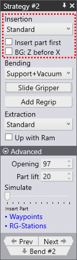
The first section of the Robotic Strategy panel controls how the part is inserted into the machine before clamping and bending.

Insert direction
Insertion

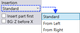
The Insertion list lets you choose between a standard insertion, where the part is inserted from the front, straight into the machine or a strategy where the part is slid in from the left or the right of the punch/die station.

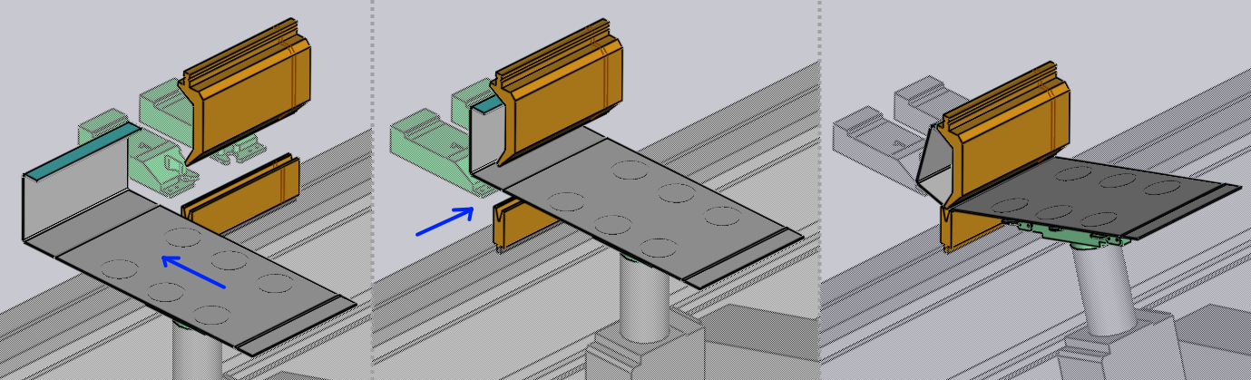
When the part has an already bent profile that needs to go into the machine, it may be difficult to get enough of a ram opening to get the part in without it colliding with the punch or die. Even when the opening may look sufficient in the simulation, a collision can occur because the part will droop in real life, especially if the overhang from the gripping point is large.

For such situations, inserting from the left or right will be useful. Here’s a couple of images showing a part being inserted from the left. Note that the beam opening in this example is insufficient to being in the part from the front, and we need to use one of these insertion directions.
Insert from Left

Insert part first

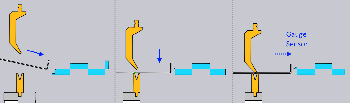
The normal insert operation works like this:
Gauge First
  1. The gauge is positioned a few mm closer to the bend line than is required for gauging the part.

  2. The part is lowered into position a few mm in front of the gauge.

  3. The robot pushes the part back against the gauge until the contact sensors in the gauge engage and indicate that the part is correctly positioned. Then the bending cycle begins.

Sometimes, if the part has a downward facing flange on which the gauging must happen, this is difficult - the flange would collide with the gauge as the part is being lowered into position. For these situations, FlexCell CAM will automatically use the Insert part first strategy, which looks like this:
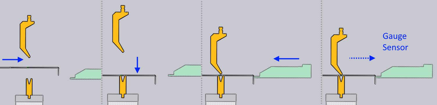
Part First
  1. The part is inserted into the machine, raised so that the down-hanging flange clears the die.

  2. The part is lowered over the die, but positioned a few mm retracted back from the final bending position.

  3. The gauge moves forward, again a few mm closer to the bend-line than is required for gauging the part.

  4. The robot now pushes back the part a few mm until the gauge contact sensors engage, and the bending then happens.

This strategy is automatically selected by FlexCell CAM when required, but selecting this checkbox allows you to override the default.

BG: Z before X

The BG: Z before X strategy creates a safer movement path for the backgauge in situations where the gauging position for this bend is closer to the bend line than the gauging position of the previous bend. Normally, the gauges will freely move from the previous gauging position to the new one once the bend step change happens.

When this checkbox is selected, the gauges first move in the Z direction until they are directly aligned behind their final positions. After that, they advance forward in the X direction to get into position, avoiding a potential collision that may be caused by a diagonal movement.

This strategy is selected automatically by FlexCell CAM where needed, but can be overridden here.

Contents

  • Insert direction
  • Insert part first
  • BG: Z before X
Robotic bending Bending

      Copyright © 2025 TRUMPF Metamation. All rights reserved.

    Compiled by Bento