
Troubleshooting
This is a troubleshooting guide that provides a concise, icon-driven reference to diagnose and fix common issues while doing simulation in the FlexCell CAM. Each table below shows an icon, its meaning, and practical steps to resolve the condition — use the "Methods to resolve the error" column as your primary action list.
Provided below a sample of Bend navigator table with errors:
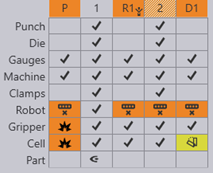
-
Bend navigator can be opened by pressing the Z key.
-
For each bend, the navigator displays several rows of status icons.
-
Icons in uncolored cells → No Errors/Warnings
-
Icons in Orange colored cells → Indicate Errors
-
Icons in Yellow colored cells → Indicate Warnings
-
-
By clicking on a cell that displays error/warning, it takes you to the simulation stage where those specific error/warning occurs.
1. Punch Row
| Icon | Meaning | Methods to resolve the error |
|---|---|---|
|
No error |
- |
|
Punch span too short |
Adjust punch length. |
|
No Punch |
Mount punch. |
|
Punch collides with part |
Change/Adjust the tool
to avoid collision; |
|
Punch collides with die |
Change/Adjust the tool
to avoid collision. |
|
Punch is overloaded beyond its rated tonnage. |
A taller punch must be used or add an adapter. |
|
Punch height is too short |
Adjust the tonnage load. Tooltip shows the actual load. |
|
Punch extends out of the press beam |
Adjust punch length, make sure it does not exceed the press beam. |


2. Die Row
Icon |
Meaning |
Methods to resolve the error |
|
No error |
- |
|
Die span too short |
Adjust die length. |
|
No Die |
Mount die. |
|
Die collides with part |
Change/Adjust the tool to avoid collision; Try changing the bend sequence |
|
Die collides with Punch |
Change/Adjust the tool to avoid collision. Make sure to choose either punch or die with less height. |
|
Die overloaded |
Change the tool having V width
greater than the previous die. |
3. Guage Row
| Icon | Meaning | Methods to resolve the error |
|---|---|---|
|
No error |
- |
|
No back gauges |
Position the gauges properly against the part. |
|
Back gauge collides with punch or die or part. |
Adjust the gauge X position. |
4. Machine Row
| Icon | Meaning | Methods to resolve the error |
|---|---|---|
|
No error |
- |
|
Part collides with floor |
It can be adjusted but lifting the component. But it should not be done. |
|
Back-gauge position exceeds the travel limits |
Position the gauges within the limits. |
|
Robot collides with machine table |
Make sure that the robot hand is away from the machine. Try changing waypoints, joint rotation. |
|
Machine overloaded |
Adjust the thickness of the part. |

5. Clamp Row
| Icon | Meaning | Methods to resolve the error |
|---|---|---|
|
No error |
- |
|
Tool not clamped properly |
Make sure the clamp is holding the tool properly. Adjust the clamp position. |

6. Robot Row
| Icon | Meaning | Methods to resolve the error |
|---|---|---|
|
No error |
- |
|
Infeasible position (Kinematic error) |
Infeasible
position is that robot cannot reach or achieve the specified position. To
rectify infeasible position error, |
|
Robot axis overtravel |
It can be resolved by changing the interpolate → Linear to Axis or vice versa; insert waypoints and adjust values. |
|
Robot collides with machine components |
Move the
waypoints to adjust the travel path. |

7. Gripper Row
| Icon | Meaning | Methods to resolve the error |
|---|---|---|
|
No error |
- |
|
Gripper collides with cell components |
Adjust gripper position to avoid collision. |
Gripper collides with floor |
Adjust gripper position to avoid collision. |
|
|
No material under suction cup |
Adjust gripper position to ensure material is under suction cup. |
|
Gripper overloaded |
Change the gripper according to the part. |

8. Cell Row
Icon |
Meaning |
Methods to resolve the error |
|
No error |
- |
|
Robot collides with cell components |
Adjust waypoints to avoid collision. |
Gripper collides with cell components |
Adjust gripper position to avoid collision. |
|
Gripper collides with floor |
Adjust gripper position to avoid collision. |
|
|
Deposit stack unstable |
Ensure the deposit stack is stable by adjusting the deposit position. |
